TR80 - Installation and Operation Guide7
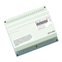
1.3.3.1 Wiring Terminals
1.3.4 Powering Up the Wall Module
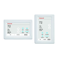
Once the wall module is installed and powered, the unit gets started shows firm-
ware version number and goes through the startup sequence to display the ready
or protected mode.
Terminals NumberLegendsDescription
1L100 to 230 V AC, 50/60 Hz
Power supply connection
2N
5
+
~
24 Vac/dc ± 10%
Power supply connection
6GND
7+RS485 Port 1
Modbus RTU slave connection to controller
8-
9COMShared common for port1 & port 2
10+RS485 Port 2
Modbus RTU repeater connection to DALI64
11-
12UIGeneral purpose universal input for
NTC10K, NTC20K, 0-10 Vdc & voltage free contact
13GND

 Loading...