Introduction
5/00 UDC3300 Expanded Model: DC330E User Manual 1
1. Introduction
1.1 Overview
The UDC 3300 is a microprocessor-based, stand-alone controller. It combines the
highest degree of functionality and operating simplicity offered in a 1/4 DIN size
controller.
With a typical accuracy of ± 0.20 % of span, the UDC 3300 is an ideal controller for
regulating temperature and other process variables in numerous heating and cooling
applications, in metal working, food, and pharmaceuticals, and testing and
environmental work.
1.2 CE Conformity (Europe)
This product is in conformity with the protection requirements of the following
European Council Directives: 73/23/EEC, the Low Voltage Directive, and
89/336/EEC, the EMC Directive. Conformity of this product with any other “CE Mark”
Directive(s) shall not be assumed.
ALM
RSP
OUT
%
1 2 3
1 2
1 2
F C
MAN
FUNCTION
LOOP 1/2
SET UP
LOWER
DISPLAY
MANUAL
AUTO
SETPOINT
SELECT
RUN
HOLD
DI
3300
SP 3300
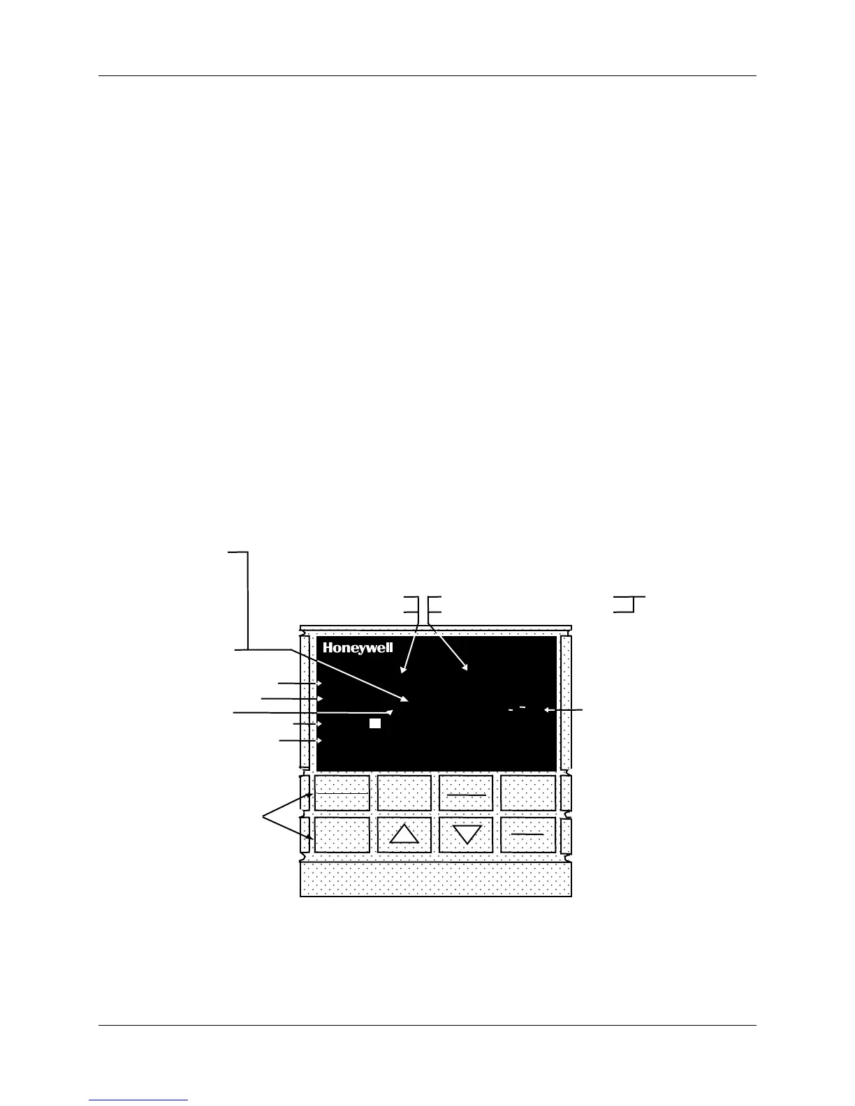
Indicator definition when lit
ALM - Alarm conditions exist
DI - Digital input active
OUT - Control relay 1 or 2 on
Upper Display - six characters
• Normal Operation - four digits dedicated to display the process variable
• Configuration Mode - displays parameter value or selection
Lower Display - eight characters
• Normal Operation - displays operating parameters and values
• Configuration Mode - displays function groups and parameters
MAN - controller in manual mode
A - controller in automatic mode
F - °Fahrenheit being used
C - °Centigrade being used
Indicator definition when lit
Deviation Bargraph
• Center bar indicates PV is
within ±1% of setpoint.
• Next bar will light if PV is
between ±1% but less than
±2% in deviation.
• If PV is equal to or greater than
±10% deviation, the center bar
plus all ten deviation bars will
light.
MAN and A off —
communications
option active
Keys - See Table 1-1
T - Accutune in progress
t - PV tune in progress
L" - Loop 2 display
I - Cascade control
C - Computer setpoint active
O - Output override active
R - Run SP ramp/program
H - Hold SP ramp/program
RSP - Remote SP or SP2 active
24157
R
3 - LSP 3 active
Figure 1-1 Operator Interface Displays and Indicators

 Loading...


