Setpoint Rate/Ramp/Soak Program Operation
62 UDC3300 Expanded Model: DC330E User Manual 5/00
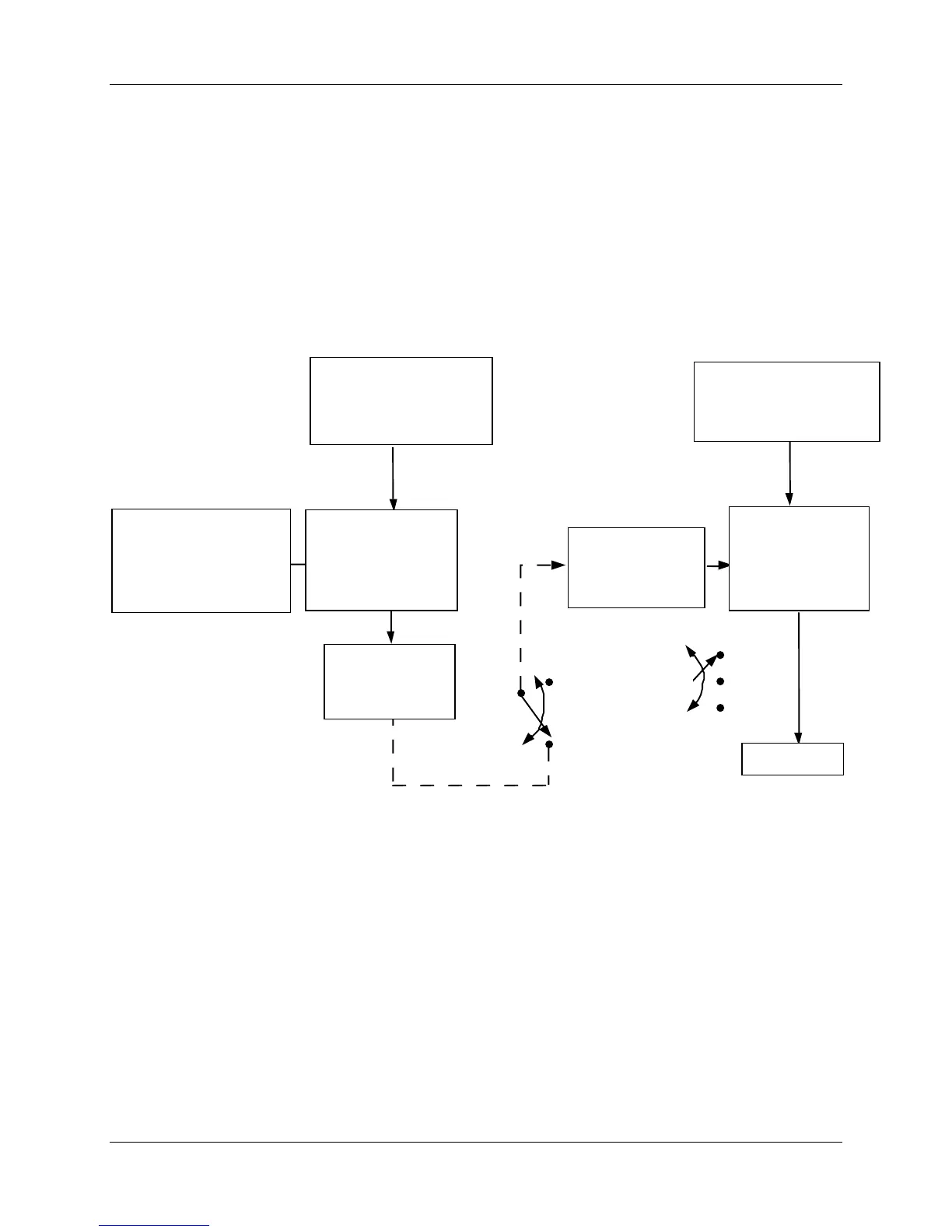
Internal Cascade Control
The following rules apply for internal Cascade control:
• Loop 2 must be the primary loop.
• Loop 1 must be the secondary (internal or slave) loop because all output forms
exist on Loop 1.
• Loop 1 remote setpoint is fixed as Loop 2 output.
• No Position Proportional output is available on cascade controllers.
PRIMARY LOOP
SECONDARY LOOP
24182
SP
2SP
3SP
PV SOURCE
See
Loop 2
Block Diagram
PV SOURCE
See
Loop 1
Block Diagram
SETPOINT
SOURCE
See
Loop #2
Block Diagram
PID
CONTROL
ALGORITHM
Loop 2
INTERNAL
OUTPUT
SIGNAL
INTERNAL CASCADE RULES
• Loop #2 must be the primary loop.
• Loop #1 must be the secondary (internal or slave) loop
because all output forms exist on Loop 1.
• Loop #1 Remote setpoint is fixed as Loop #2 output.
PID
CONTROL
ALGORITHM
Loop 1
SETPOINT
SOURCE
Loop #1
OUTPUT
To Final
Control
Element
Figure 4-2 Functional Overview Block Diagram of Internal Cascade of a
2-loop Controller

 Loading...


