Installation
6 UDC3300 Expanded Model: DC330E User Manual 5/00
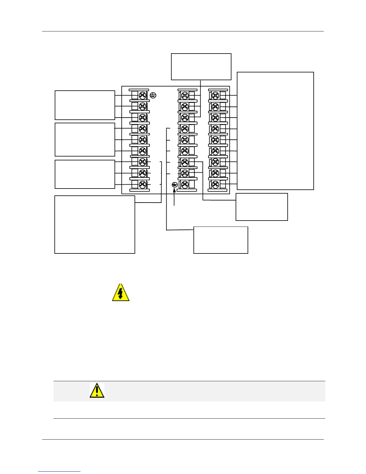
Composite Wiring
1
2
3
4
5
6
7
8
9
L1
L2/N
22
23
24
Auxiliary Output
Terminals
See Figure 2-14
Outputs and Alarms
Terminals
•
Time Proportional Output
See Figures 2-7, 2-8, 2-9,
2-10
• Current Output/Universal
Output
See Figures 2-11, 2-12
•
Position Proportional
Output
See Figure 2-13
For Control and Alarm Relay
Contact information, See
Tables 2-3 and 2-4.
Digital Inputs
Terminals
See Figure 2-15
AC Line Voltage
Terminals
See Figure 2-4
Input #2 Terminals
See Figure 2-5
Input #1
Terminals
See Figure 2-5
10
11
12
13
14
15
16
17
Communications
Terminals
See Figure 2-16
Transmitter Power for
4-20 mA 2-wire
Transmitters
•
Using Alarm 2 Output
See Figure 2-17
•
Using Auxiliary Output
See Figure 2-18
I/O shield ground
(Do not use for
Communications shield)
25
26
27
Two HLAI Terminals
See Figure 2-6
Figure 2-3 Composite Wiring Diagram
Line Voltage Wiring
This equipment is suitable for connection to 90-264 Vac or 24 Vac/dc, 50/60 Hz,
power supply mains. It is the user’s responsibility to provide a switch and non-time
delay (North America), quick-acting, high breaking capacity, Type F, (Europe) 1/2 A,
250 V fuse(s) or circuit-breaker for 90-264 V; or 1 A, 125 V fuse or circuit breaker for
24 Vac/dc operation, as part of the installation. The switch or circuit-breaker should
be located close to the controller, within easy reach of the operator. The switch or
circuit-breaker should be marked as the disconnecting device for the controller
(4 mm
2
).
CAUTION
Applying 90-264 Vac to a controller rated for 24 Vac/dc will severely damage the controller
and is a fire and smoke hazard.

 Loading...


