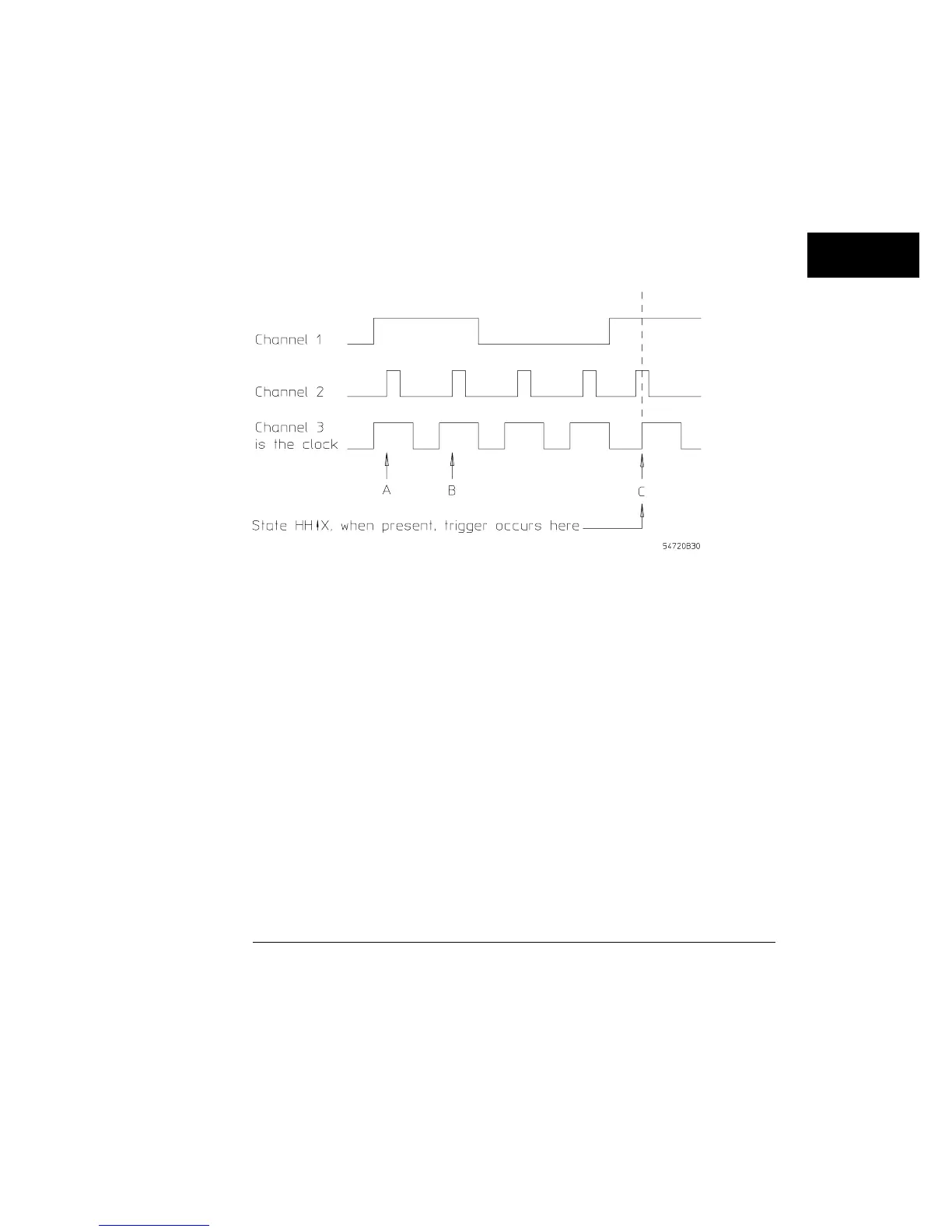
Figure 18-5 shows a three-channel timing diagram. For this example, the
clock is a rising edge on channel 3. The oscilloscope was also set to look for
when a pattern is present, and the oscilloscope is looking for a high on
channels 1 and 2. You may notice that channels 1 and 2 are both high during
clock pulses A, B, and C. In the state mode, the pattern is checked for
validity only on the selected clock edge. On the rising edge of clock pulses A
and B, channel 2 is a low level. Therefore, the pattern is valid only on the
rising edge of clock pulse C.
Example of a when a trigger occurs on a state timing diagram
Figure 18-5
Trigger Menu
Mode
18–13