Not all 1-M
Ω
divider probes work with all 1-M
Ω
oscilloscope inputs. The
probe data sheet shows the range of oscilloscope input capacitance it can
accommodate. You must make sure that the input capacitance of the
oscilloscope is within that range.
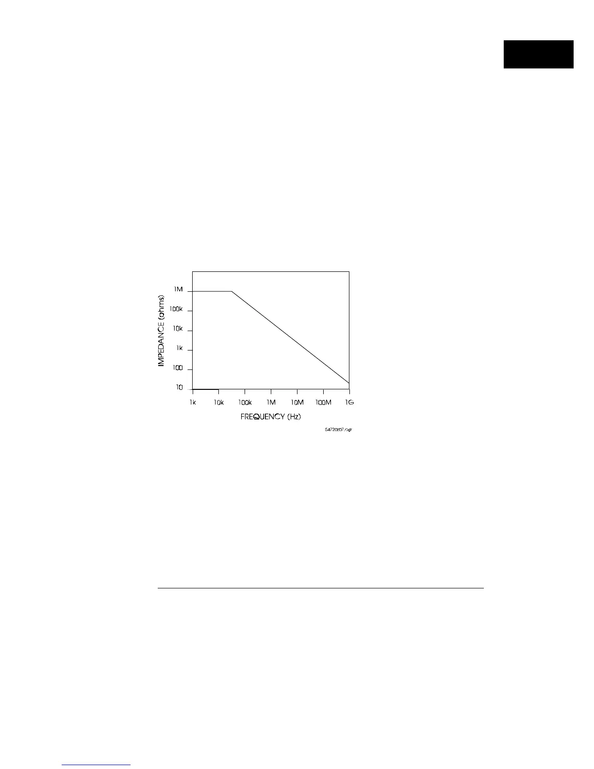
The advantage of this type of probe is that it has the highest resistance. Its
disadvantages are that it has the highest capacitive loading and the lowest
bandwidth. At 2 MHz, the impedance of an 8-pF capacitance is 10 k
Ω
, and at
100 MHz it is only 200
Ω
. This type of probe is often referred to as a "high
impedance" probe. This is a misnomer because they exhibit high impedance
only at relatively low frequencies. Figure 1-13 shows a plot of the impedance
of a typical 1-M
Ω
, 8-pF probe as a function of frequency.
Some applications where 1-M
Ω
(or higher) probes are appropriate include
high-impedance nodes (
≥
10-k
Ω
), and summing junctions in operational
amplifiers where the junction voltage is not at dc ground.
Impedance of a 1-M
Ω
, 8 pF probe versus frequency
Figure 1-13
How the Oscilloscope Works
System Bandwidth
1–29