224
Configuring sFlow example
Network requirements
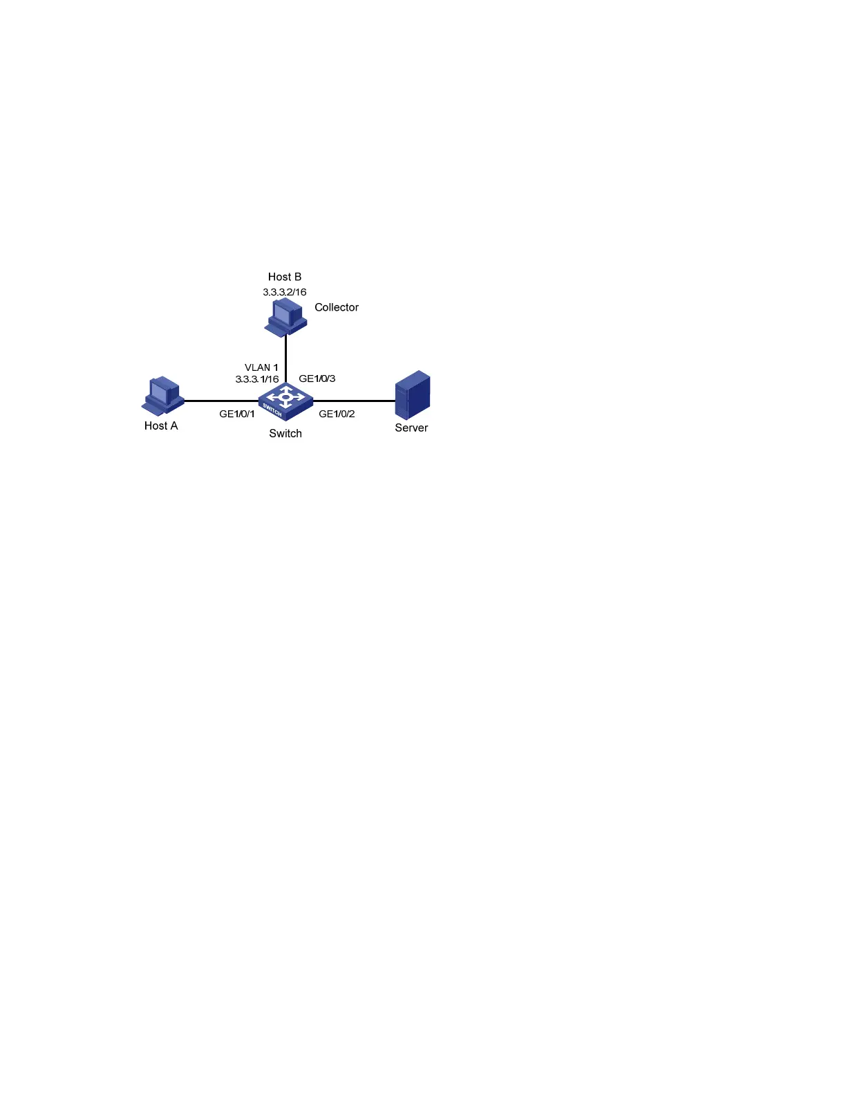
As shown in Figure 81, Host A is connected with Server through Switch (sFlow agent).
Enable sFlow (including flow sampling and counter sampling) on GigabitEthernet 1/0/1 to monitor
traffic on the port. The Switch sends sFlow packets through GigabitEthernet 1/0/3 to the sFlow collector,
which analyzes the sFlow packets and displays results.
Figure 81 Network diagram for sFlow configuration
Configuration procedure
1. Configure the sFlow agent and sFlow collector
# Configure the IP address of Vlan-interface 1 on Switch as 3.3.3.1/16.
<Switch> system-view
[Switch] interface vlan-interface 1
[Switch-Vlan-interface1] ip address 3.3.3.1 16
[Switch-Vlan-interface1] quit
# Specify the IP address for the sFlow agent.
[Switch] sflow agent ip 3.3.3.1
# Specify sFlow collector ID 2, IP address 3.3.3.2, the default port number, and description of netserver
for the sFlow collector.
[Switch] sflow collector 2 ip 3.3.3.2 description netserver
2. Configure counter sampling
# Set the counter sampling interval to 120 seconds.
[Switch] interface gigabitethernet 1/0/1
[Switch-GigabitEthernet1/0/1] sflow counter interval 120
# Specify sFlow collector 2 for counter sampling.
[Switch-GigabitEthernet1/0/1] sflow counter collector 2
3. Configure flow sampling
# Set the Flow sampling mode and sampling rate.
[Switch-GigabitEthernet1/0/1] sflow sampling-mode random
[Switch-GigabitEthernet1/0/1] sflow sampling-rate 4000
# Specify sFlow collector for flow sampling.
[Switch-GigabitEthernet1/0/1] sflow flow collector 2