159
To do… Use the command… Remarks
Display the information of
candidate devices
display cluster candidates [ mac-
address mac-address | verbose ]
[ | { begin | exclude | include }
regular-expression ]
Display the current topology
information
display cluster current-topology
[ mac-address mac-address [ to-
mac-address mac-address ] |
member-id member-number [ to-
member-id member-number ] ] [ |
{ begin | exclude | include }
regular-expression ]
Display the information about
cluster members
display cluster members [ member-
number | verbose ] [ | { begin |
exclude | include } regular-
expression ]
Clear NDP statistics
reset ndp statistics [ interface
interface-list ]
Available in user view
Configuring cluster management example
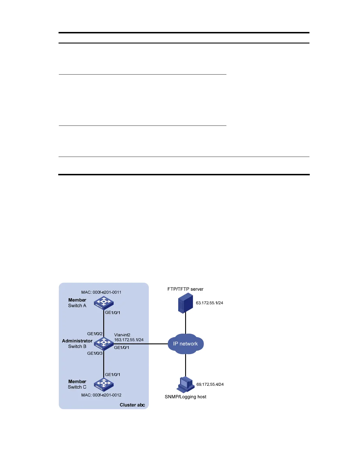
Network requirements
• Three switches form cluster abc, whose management VLAN is VLAN 10. In the cluster, Switch B
serves as the management device (Administrator), whose network management interface is VLAN-
interface 2; Switch A and Switch C are the member devices (Member).
• All devices in the cluster use the same FTP server and TFTP server on host 63.172.55.1/24, and use
the same SNMP NMS and log services on host IP address: 69.172.55.4/24.
• Add the device whose MAC address is 000f-e201-0013 to the blacklist.
Figure 62 Network diagram for cluster management configuration