105
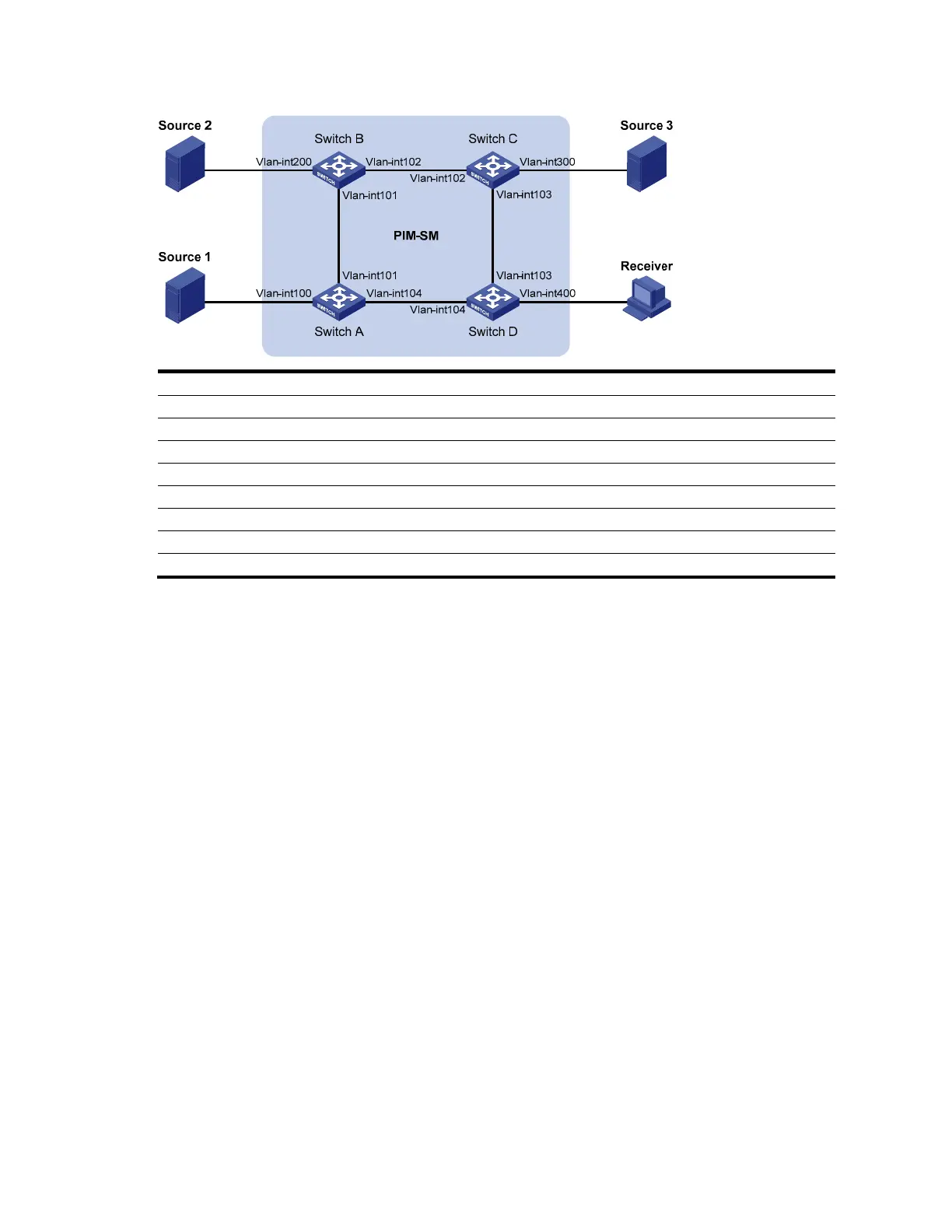
Figure 34 Network diagram for IGMP SSM mapping configuration
Device Interface IP address Device Interface IP address
Source 1 — 133.133.1.1/24 Source 3 — 133.133.3.1/24
Source 2 — 133.133.2.1/24 Receiver — 133.133.4.1/24
Switch A Vlan-int100 133.133.1.2/24 Switch C Vlan-int300 133.133.3.2/24
Vlan-int101 192.168.1.1/24 Vlan-int103 192.168.3.1/24
Vlan-int104 192.168.4.2/24 Vlan-int102 192.168.2.2/24
Switch B Vlan-int200 133.133.2.2/24 Switch D Vlan-int400 133.133.4.2/24
Vlan-int101 192.168.1.2
24 Vlan-int103 192.168.3.2
24
Vlan-int102 192.168.2.1/24 Vlan-int104 192.168.4.1/24
Configuration procedure
1. Configure IP addresses and unicast routing
Configure the IP address and subnet mask of each interface according to Figure 34. Th
e detailed
configuration steps are omitted here.
Configure OSPF for interoperability among the switches. Ensure the network-layer interoperation on the
PIM-SM domain and dynamic update of routing information among the switches through a unicast
routing protocol. The detailed configuration steps are omitted here.
2. Enable IP multicast routing, enable PIM-SM on each interface, and enable IGMP and IGMP SSM
mapping on the host-side interface.
# Enable IP multicast routing on Switch D, enable PIM-SM on each interface, and enable IGMPv3 and
IGMP SSM mapping on VLAN-interface 400.
<SwitchD> system-view
[SwitchD] multicast routing-enable
[SwitchD] interface vlan-interface 400
[SwitchD-Vlan-interface400] igmp enable
[SwitchD-Vlan-interface400] igmp version 3
[SwitchD-Vlan-interface400] igmp ssm-mapping enable
[SwitchD-Vlan-interface400] pim sm
[SwitchD-Vlan-interface400] quit
[SwitchD] interface vlan-interface 103
[SwitchD-Vlan-interface103] pim sm
[SwitchD-Vlan-interface103] quit
[SwitchD] interface vlan-interface 104

 Loading...


