108
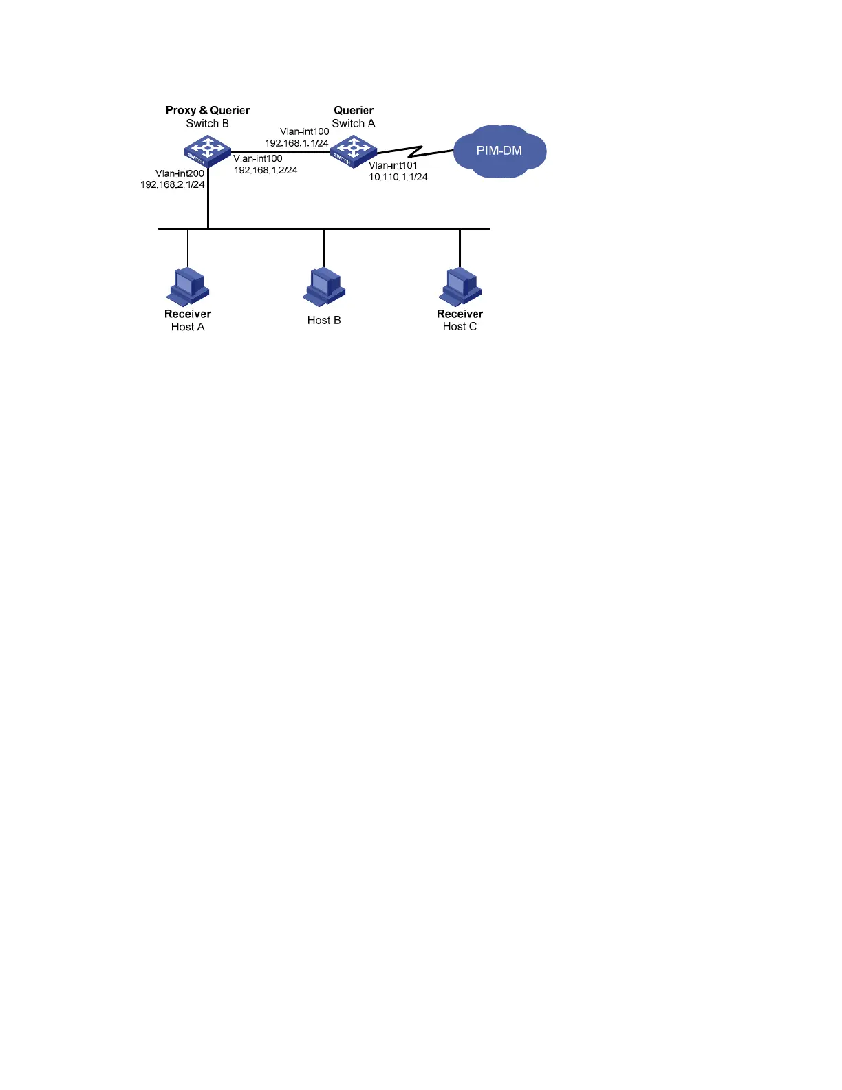
Figure 35 Network diagram for IGMP Proxying configuration
Configuration procedure
1. Configure IP addresses
Configure the IP address and subnet mask of each interface according to Figure 35. Th
e detailed
configuration steps are omitted here.
2. Enable IP multicast routing, PIM-DM, IGMP, and IGMP Proxying.
# Enable IP multicast routing on Switch A, PIM-DM on VLAN-interface 101, and IGMP on VLAN-interface
100.
<SwitchA> system-view
[SwitchA] multicast routing-enable
[SwitchA] interface vlan-interface 101
[SwitchA-Vlan-interface101] pim dm
[SwitchA-Vlan-interface101] quit
[SwitchA] interface vlan-interface 100
[SwitchA-Vlan-interface100] igmp enable
[SwitchA-Vlan-interface100] pim dm
[SwitchA-Vlan-interface100] quit
# Enable IP multicast routing on Switch B, IGMP Proxying on VLAN-interface 100, and IGMP on VLAN-
interface 200.
<SwitchB> system-view
[SwitchB] multicast routing-enable
[SwitchB] interface vlan-interface 100
[SwitchB-Vlan-interface100] igmp proxying enable
[SwitchB-Vlan-interface100] quit
[SwitchB] interface vlan-interface 200
[SwitchB-Vlan-interface200] igmp enable
[SwitchB-Vlan-interface200] quit
3. Verify the configuration
Use the display igmp interface command to view the IGMP configuration and operation information on
an interface. For example
# Display the IGMP configuration and operation information on VLAN-interface 100 of Switch B.
[SwitchB] display igmp interface vlan-interface 100 verbose

 Loading...


