401
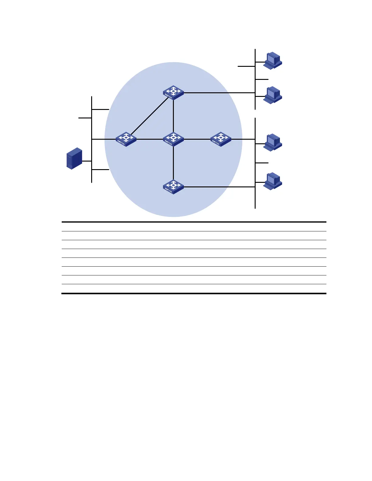
Figure 103 Network diagram for IPv6 PIM-SSM configuration
Ethernet
EthernetEthernet
Source
4001::100/64
IPv6 PIM-SM
Switch A
Switch B
Switch C
Switch D
Receiver
Host A
Host B
Host C
Host D
Receiver
N1N2
Switch E
Vlan-int100
Vlan-int200
Vlan-int200
Vlan-int300
Vlan-int102
Vlan-int102
Vlan-in
t1
01
Vlan-
int10
1
Vlan-int103
Vlan-int103
Vlan-int104
Vlan-int104
Vlan-int105
Vlan-int105
Device Interface IP address Device Interface IP address
Switch A Vlan-int100 1001::1/64 Switch D Vlan-int300 4001::1/64
Vlan-int101 1002::1/64 Vlan-int101 1002::2/64
Vlan-int102 1003::1/64 Vlan-int105 4002::1/64
Switch B Vlan-int200 2001::1/64 Switch E Vlan-int104 3001::2/64
Vlan-int103 2002::1/64 Vlan-int103 2002::2/64
Switch C Vlan-int200 2001::2/64 Vlan-int102 1003::2/64
Vlan-int104 3001::1/64 Vlan-int105 4002::2/64
Configuration procedure
1. Enable IPv6 forwarding, and configure IPv6 addresses and IPv6 unicast routing.
Enable IPv6 forwarding on each switch, and configure the IPv6 address and prefix length for each
interface according to Figure 103 (details not shown).
Configure OSPFv3 on the switches in the IPv6 PIM-DM domain to ensure network-layer reachability
among them (details not shown).
2. Enable IPv6 multicast routing, and enable IPv6 PIM-SM and MLD.
# Enable IPv6 multicast routing on Switch A, enable IPv6 PIM-SM on each interface, and run MLDv2 on
VLAN-interface 100, which connects Switch A to N1.
<SwitchA> system-view
[SwitchA] multicast ipv6 routing-enable
[SwitchA] interface vlan-interface 100
[SwitchA-Vlan-interface100] mld enable
[SwitchA-Vlan-interface100] mld version 2
[SwitchA-Vlan-interface100] pim ipv6 sm

 Loading...


