61
Network diagram
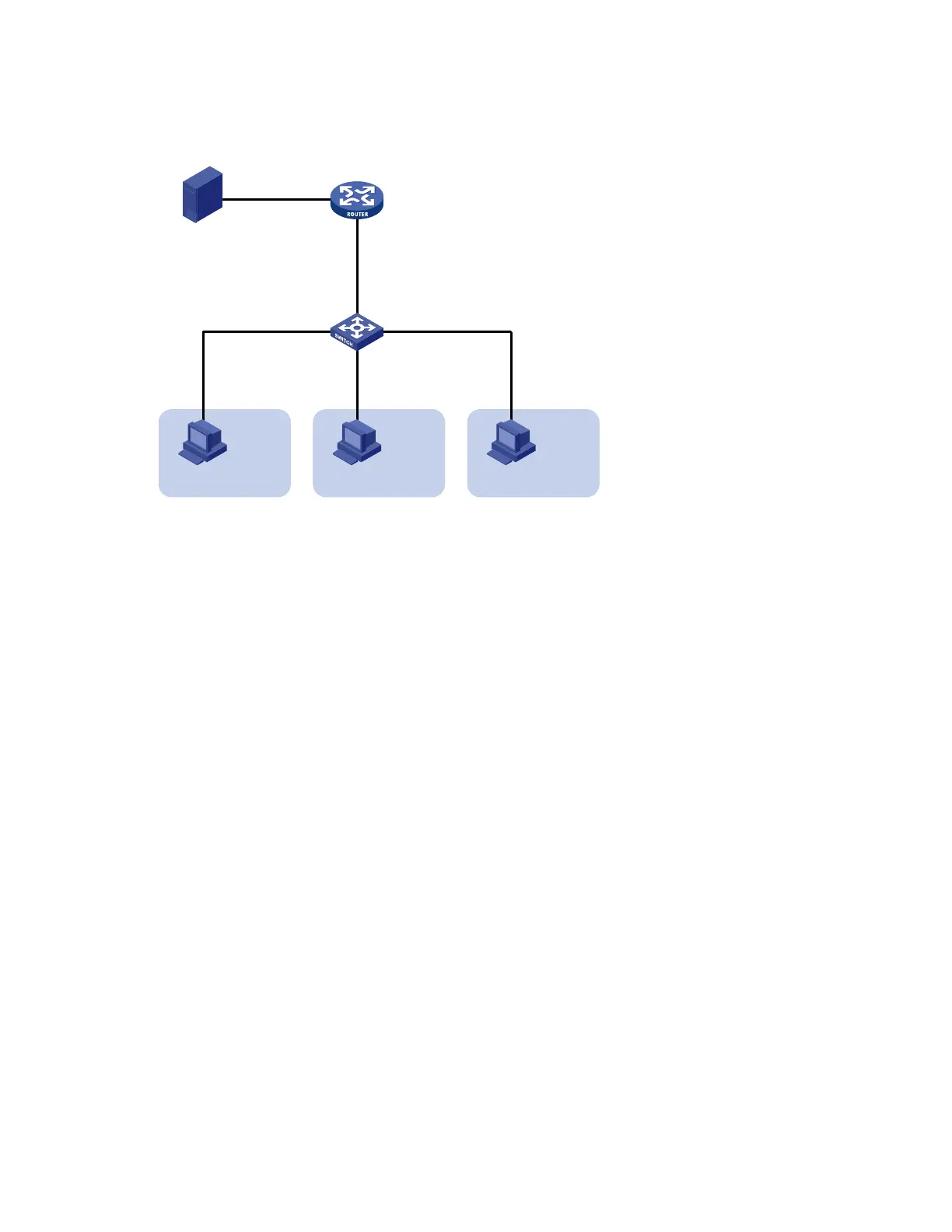
Figure 22 Network diagram for sub-VLAN-based multicast VLAN configuration
Source
Receiver
Host A
VLAN 2
GE1/0/2
GE1/0/3
GE1/0/4
Switch A
IGMP querier
Router A
GE1/0/1
1.1.1.2/24
GE1/0/2
10.110.1.1/24
1.1.1.1/24
Receiver
Host B
VLAN 3
Receiver
Host C
VLAN 4
GE1/0/1
Configuration procedure
1. Configure IP addresses
Configure an IP address and subnet mask for each interface according to Figure 22 (details not shown).
2. Configure Router A
# Enable IP multicast routing, enable PIM-DM on each interface and enable IGMP on the host-side
interface GigabitEthernet 1/0/2.
<RouterA> system-view
[RouterA] multicast routing-enable
[RouterA] interface gigabitethernet 1/0/1
[RouterA-GigabitEthernet1/0/1] pim dm
[RouterA-GigabitEthernet1/0/1] quit
[RouterA] interface gigabitethernet 1/0/2
[RouterA-GigabitEthernet1/0/2] pim dm
[RouterA-GigabitEthernet1/0/2] igmp enable
3. Configure Switch A
# Enable IGMP snooping globally.
<SwitchA> system-view
[SwitchA] igmp-snooping
[SwitchA-igmp-snooping] quit
# Create VLAN 2 and assign GigabitEthernet 1/0/2 to this VLAN.
[SwitchA] vlan 2
[SwitchA-vlan2] port gigabitethernet 1/0/2
[SwitchA-vlan2] quit
The configuration for VLAN 3 and VLAN 4 is similar to the configuration for VLAN 2.

 Loading...


