Chapter 2
Upgrade Procedures for 1.1 GHz mx2 Dual Processors (A9730A)
Introduction
33
Ensure that all processors are rated for use at the same speed. Failure to observe this caution
will result in performance degradation.
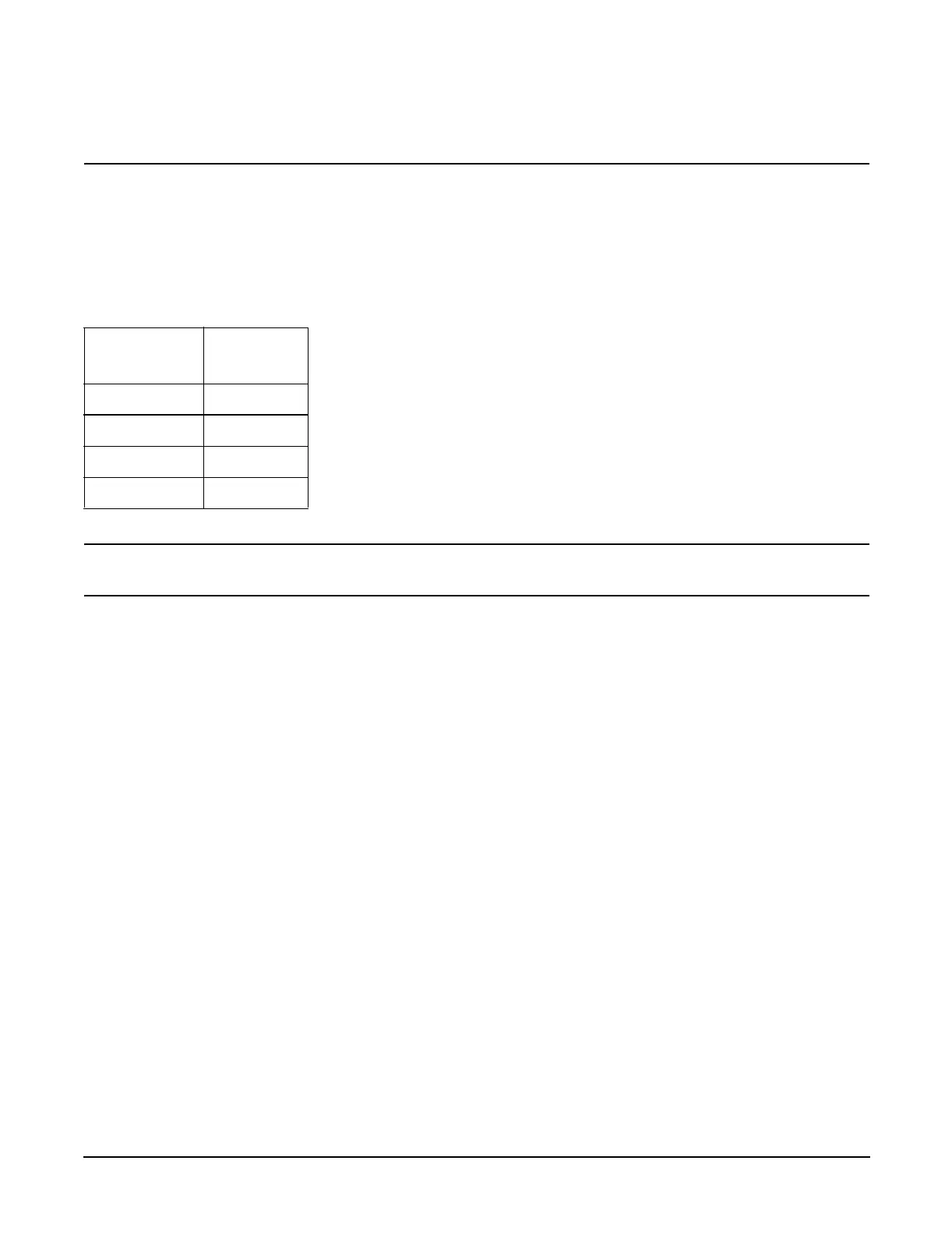
Processor Load Order
Processor modules are housed on the processor extender board located under the top cover in the top service
bay. The processor extender board can hold between one and four processor modules. CPU 0 and CPU 1 are
located on the top of the processor extender board and CPU 2 and CPU 3 are located on the bottom.
Processors must be installed in a specific order.
CAUTION Do not modify the settings of the DIP switches located on the processor extender board. These
switches are for factory use. Failure to observe this caution will result in system failure.
Removing a Processor
To remove a processor on the processor extender board, perform the following steps:
Step 1. Unplug the processor cable from its socket on the extender board.
Step 2. Using the CPU install tool from the upgrade kit, loosen the 6, T15 shoulder screws that attach the
sequencer frame on the heatsink, until the sequencer frame is free.
Step 3. Remove the sequencer frame from the heatsink.
Step 4. Unlock the assembly to the socket by rotating the cam on the socket 180 degrees counterclockwise,
using the CPU install tool from the upgrade kit.
Step 5. Ensure the cam on the processor socket lock is in the unlocked, counterclockwise position.
Step 6. Carefully remove the processor from the processor socket.
Installing a Processor
To install a processor on the extender board, perform the following steps:
Prior to installing a processor into your system, read the following instructions carefully and refer to
Figure 2-3, “Installing Processor on Extender Board,” for a complete understanding of this process.
Step 1. Ensure the cam on the processor socket lock is in the unlocked, counterclockwise position.
Step 2. Carefully lower the processor, without the sequencer clamp, onto the processor socket. Align the
pins on the bottom of the heatsink to the slots in the retention frame on the extender board.
Table 2-1 Processor Load Order
Processor
Modules
Socket
First CPU 0
Second CPU 1
Third CPU 2
Fourth CPU 3
 Loading...


