Figures
7
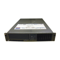
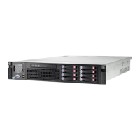
Figure 1-1. hp Integrity rx4640 Server . . . . . . . . . . . . . . . . . . . . . . . . . . . . . . . . . . . . . . . . . . . . . . . . . 9
Figure 1-2. Accessing 25MM Torx Screws . . . . . . . . . . . . . . . . . . . . . . . . . . . . . . . . . . . . . . . . . . . . . 13
Figure 1-3. Pedestal mounted hp Integrity rx4640 Server . . . . . . . . . . . . . . . . . . . . . . . . . . . . . . . . 14
Figure 1-4. Removing and Installing the Front Bezel . . . . . . . . . . . . . . . . . . . . . . . . . . . . . . . . . . . . 15
Figure 1-5. Removing and Installing the Front Cover . . . . . . . . . . . . . . . . . . . . . . . . . . . . . . . . . . . . 17
Figure 1-6. Removing and Installing the Top Cover . . . . . . . . . . . . . . . . . . . . . . . . . . . . . . . . . . . . . 19
Figure 1-7. Processor Extender Board . . . . . . . . . . . . . . . . . . . . . . . . . . . . . . . . . . . . . . . . . . . . . . . . 22
Figure 1-8. Memory Extender Board Latches . . . . . . . . . . . . . . . . . . . . . . . . . . . . . . . . . . . . . . . . . . 25
Figure 1-9. Memory Extender Board . . . . . . . . . . . . . . . . . . . . . . . . . . . . . . . . . . . . . . . . . . . . . . . . . 25
Figure 1-10. Hot-Swap I/O Chassis Fans Removal and Replacement. . . . . . . . . . . . . . . . . . . . . . . . 27
Figure 2-1. Processor Cable Placed Correctly . . . . . . . . . . . . . . . . . . . . . . . . . . . . . . . . . . . . . . . . . . 35
Figure 2-2. Processor Cable Placed Incorrectly . . . . . . . . . . . . . . . . . . . . . . . . . . . . . . . . . . . . . . . . . 35
Figure 2-3. Installing Processor on Extender Board . . . . . . . . . . . . . . . . . . . . . . . . . . . . . . . . . . . . . 38
Figure 2-4. IO Baseboard Select Switches . . . . . . . . . . . . . . . . . . . . . . . . . . . . . . . . . . . . . . . . . . . . . 39
Figure 3-1. Processor Cable Placed Correctly . . . . . . . . . . . . . . . . . . . . . . . . . . . . . . . . . . . . . . . . . . 45
Figure 3-2. Processor Cable Placed Incorrectly . . . . . . . . . . . . . . . . . . . . . . . . . . . . . . . . . . . . . . . . . 45
Figure 3-3. Installing Processor on Extender Board . . . . . . . . . . . . . . . . . . . . . . . . . . . . . . . . . . . . . 47
Figure 3-4. IO Baseboard Select Switches . . . . . . . . . . . . . . . . . . . . . . . . . . . . . . . . . . . . . . . . . . . . . 48
Figure 4-1. Memory Extender Board Latches . . . . . . . . . . . . . . . . . . . . . . . . . . . . . . . . . . . . . . . . . . 53
Figure 4-2. Memory Extender Board . . . . . . . . . . . . . . . . . . . . . . . . . . . . . . . . . . . . . . . . . . . . . . . . . 54
Figure 4-3. 16 DIMM Extender Board Slot IDs . . . . . . . . . . . . . . . . . . . . . . . . . . . . . . . . . . . . . . . . . 58
Figure 4-4. 32 DIMM Extender Board Slot IDs . . . . . . . . . . . . . . . . . . . . . . . . . . . . . . . . . . . . . . . . . 58
Figure 4-5. Inserting DIMM into Extender Board Slot . . . . . . . . . . . . . . . . . . . . . . . . . . . . . . . . . . . 59
Figure 5-1. SCSI Cable B Connection to the SCSI Backplane . . . . . . . . . . . . . . . . . . . . . . . . . . . . . 63
Figure 5-2. Replacing the SCSI Duplex Board . . . . . . . . . . . . . . . . . . . . . . . . . . . . . . . . . . . . . . . . . 64
Figure 5-3. Replacing the SCSI Jumper Cable . . . . . . . . . . . . . . . . . . . . . . . . . . . . . . . . . . . . . . . . . 65
Figure 5-4. SCSI Backplane Removal and Replacement . . . . . . . . . . . . . . . . . . . . . . . . . . . . . . . . . . 66
Figure 5-5. Installing the SCSI Duplex Board . . . . . . . . . . . . . . . . . . . . . . . . . . . . . . . . . . . . . . . . . . 67
Figure 5-6. Installing SCSI Cable B to the SCSI Adapter Board . . . . . . . . . . . . . . . . . . . . . . . . . . . 68
Figure 5-7. Unplugging SCSI B Cable from the SCSI Backplane. . . . . . . . . . . . . . . . . . . . . . . . . . . 71
Figure 5-8. Unplugging SCSI B Cable from the SCSI Adapter Board . . . . . . . . . . . . . . . . . . . . . . . 72
Figure 5-9. Removing the Duplex Board. . . . . . . . . . . . . . . . . . . . . . . . . . . . . . . . . . . . . . . . . . . . . . . 73
Figure 5-10. Installing the SCSI Jumper Cable . . . . . . . . . . . . . . . . . . . . . . . . . . . . . . . . . . . . . . . . 74
Figure 6-1. Accessing 25MM Torx Screws . . . . . . . . . . . . . . . . . . . . . . . . . . . . . . . . . . . . . . . . . . . . . 78
Figure 6-2. Pedestal Mounted hp Integrity rx4640 Server . . . . . . . . . . . . . . . . . . . . . . . . . . . . . . . . 79
Figure 6-3. Removing and Replacing the Top Cover . . . . . . . . . . . . . . . . . . . . . . . . . . . . . . . . . . . . . 80
Figure 6-4. Slot ID Numbering . . . . . . . . . . . . . . . . . . . . . . . . . . . . . . . . . . . . . . . . . . . . . . . . . . . . . . 82
Figure 6-5. LAN I/O Card Latch Location . . . . . . . . . . . . . . . . . . . . . . . . . . . . . . . . . . . . . . . . . . . . . 83
Figure 6-6. Inserting LAN I/O Card. . . . . . . . . . . . . . . . . . . . . . . . . . . . . . . . . . . . . . . . . . . . . . . . . . 84
Figure 6-7. Slot ID Numbering . . . . . . . . . . . . . . . . . . . . . . . . . . . . . . . . . . . . . . . . . . . . . . . . . . . . . . 85
Figure 6-8. SCSI I/O Card latch Location . . . . . . . . . . . . . . . . . . . . . . . . . . . . . . . . . . . . . . . . . . . . . 86
Figure 6-9. Inserting SCSI I/O Card . . . . . . . . . . . . . . . . . . . . . . . . . . . . . . . . . . . . . . . . . . . . . . . . . 87

 Loading...


