31
[DeviceB] display ntp-service ipv6 sessions
Notes: 1 source(master), 2 source(peer), 3 selected, 4 candidate, 5 configured.
Source: [1234]3000::35
Reference: 127.127.1.0 Clock stratum: 2
Reachabilities: 15 Poll interval: 64
Last receive time: 19 Offset: 0.0
Roundtrip delay: 0.0 Dispersion: 0.0
Total sessions: 1
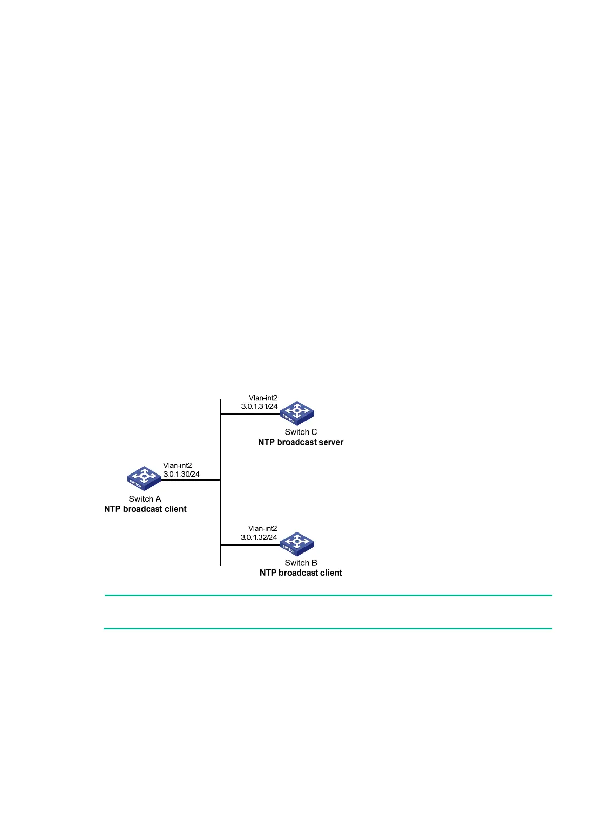
NTP broadcast mode configuration example
Network requirements
As shown in Figure 12, Switch C functions as the NTP server for multiple devices on a network
segment and synchronizes the time among multiple devices.
• Configure Switch C's local clock as a reference source, with the stratum level 2.
• Configure Switch C to operate in broadcast server mode and send out broadcast messages
from VLAN-interface 2.
• Configure Switch A and Switch B to operate in broadcast client mode, and listen to broadcast
messages through VLAN-interface 2.
Figure 12 Network diagram
NOTE:
In this example, Switch B must be a switch that supports IPv4 multicast routing.
Configuration procedure
1. Set the IP address for each interface, and make sure Switch A, Switch B, and Switch C can
reach each other, as shown in Figure 12. (Details
not shown.)
2. Configure Switch C:
# Enable the NTP service.
<SwitchC> system-view
[SwitchC] ntp-service enable
# Specify the local clock as the reference source, with the stratum level 2.

 Loading...