Shenzhen Hpmont Technology Co., Ltd Chapter 6 Function Introduction
HD30 Series Inverters User Manual ―103―
No. Name Description Range
factory setting
F16.04 Analogue input AI4 function selection 0
8
0
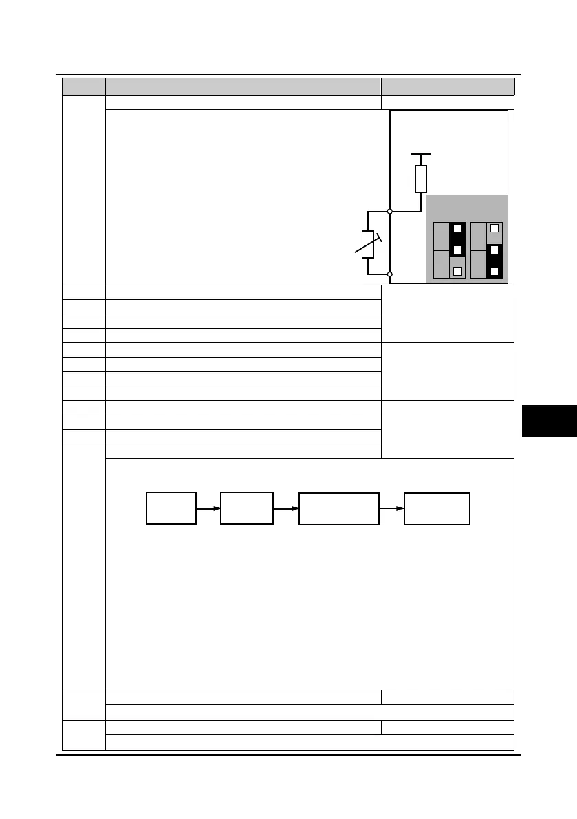
8: Motor overheating signal input.
• Connect electronic thermistor embedded
motor stator coils to the inverter’s
analogue input, as the right figure.
• Refer to parameters F20.06 and F20.07
about the thermistor.
• Refer to parameters F16.00-F16.03
about the range of 1-7.
Note: Only when using HD30-EIO will F16.03
and F16.04 (analogue inputs AI3 and AI4) be
enabled.
F16.05 Analogue input AI1 bias -100.0
100.0
0.0%
F16.11 Analogue input AI3 bias
F16.06 Analogue input AI1 gain -10.00
10.00
1.00
F16.12 Analogue input AI3 gain
F16.07 Analogue input AI1 filtering time 0.01
10.00
0.05s
Analogue input AI2 filtering time
F16.13 Analogue input AI3 filtering time
Analogue input AI4 filtering time
When select AI1-AI4 inputs as open-loop frequency setting source, the relationship between the
analogue input and the setting frequency is shown as figure:
The analogue voltage reasults from setting frequency signal disposed by analogue input filtering, bias
and gain. The relationship between the analogue voltage and the setting frequency is set by
parameters of Group F05.
• Analogue input gain and bias are involved in analogue calculation is as following formula: Y=kX+b
• Here: Y is the calculated analogue, X is the value before adjusting, k is the analogue input gain
(F16.06, F16.09, F16.12, F16.15), and b is the analogue input bias (F16.05, F16.08, F16.11,
F16.14).
• F16.07, F16.10, F16.13, F16.16 define the filtering time. It is used to filter the analogue signal.The
longer the filter time is, the higher the immunity level is, but the response time is prolonged. That
is, the shorter the filter time is, the quicker the response time is, but the lower the immunity level.
Note: Only when using HD30-EIO will F16.11
F16.16 (analogue inputs AI3 and AI4) be
enabled.
Maximum input pulse frequency
When set the DI6 terminal as pulse input, F16.17 defines the maximum input pulse frequency.
Input pulse filtering time
It is used to filter the input pulse frequency and filter out the small fluctuations in the pulse frequency.
HD30-EIO
+5V
10k
AI4+
AI4-
CN4
1
3
CN3
1
3
V
I
V
R
Thermistor
Jumper setting
Analogue
actual value
Analogue
input filtering
Analogue input gain
Analogue input bias
Analogue value
after computing
6

 Loading...


