Chapter 4 Electrical Installation Shenzhen Hpmont Technology Co., Ltd
―32― HD30 Series Inverters User Manual
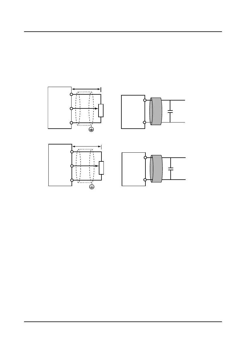
Wiring of analogue input terminal
The AI1 is voltage input and the voltage input range is 0
-
10V. Its connection and disposal are
shown in Figure 4-19.
The AI2 is selectable voltage/current input, the input range are -10
-
+10V/0
-
20mA. Its
connection and disposal are shown in Figure 4-20.
The input voltage signal can use the control board of internal +/-10V, or be provided by the
external.
Figure 4-19 AI1 input terminal connection and disposal
Figure 4-20 AI2 input terminal connection and disposal
The analogue input signal is a weak electrical signal, which is vulnerable to external interference.
Therefore the shielded cable is required to use, which is no more than 50 meters and should be
reliably grounded. In some more serious interference occasions, the analog input signal is
needed to add the filter capacitor or ferrite ring.
AI1
GND
0.022uF
50V
Less than 50 m
GND
PE
AI1
+10
Ferrite core
Signal line winding on the
ferrite core about 2 or 3 turns
Filter capacitor
Control
Board
Control
Board
Potentiometer
AI2
GND
0.022uF
50V
GND
AI2
+10
PE
Ferrite core
Signal line winding on the
ferrite core about 2 or 3 turns
Filter capacitor
Control
Board
Control
Board
Potentiometer
 Loading...


