CONNECTING A WEATHER SENSOR (OPTIONAL AND NOT INCLUDED)
The I-Core controller has the ability of connecting two Hunter Sensors
(three with I-Core Metal) including:
• Mini-Clik
®
• Rain Clik
™
(including Wireless Rain Clik, Wireless Rain Freeze-Clik)
• Freeze-Clik
®
• Wind-Clik
®
• Mini-Weather Station (MWS)
• Solar Sync and Wireless Solar Sync ET Sensor
With the I-Core controller, Clik sensors can be programmed to shut down
individual stations, not necessarily the entire controller. Each sensor can be
given its own response instructions according to each station. Hunter Clik
sensors are usually normally closed, and open on alarm. This signals the
controller to suspend watering when precipitation, freeze or wind events
occur. The sensor connects directly to the sensor terminals, which also
allows you to override the sensor by using the Rain Sensor bypass switch
on the face of the controller.
1. To connect Clik sensors, locate the 2 pairs of sensor terminals in the
Power and Accessory Terminal section, labeled S1, S1 and S2, S2 (S3
available on I-Core Metal).
2. Route the wires from the Clik sensor through any of the available
knockouts into the controller cabinet.
3. The sensor connections are made in dedicated pairs. Remove the
sensor jumper wire from one pair of S1 or S2 terminals. Attach one
sensor wire to each of the two S1
or S2 terminals.
4. To connect the Wireless Rain Clik or Wireless Rain Freeze Clik, the
blue and white wires will be connected to the corresponding sensor
terminal as stated above: One into the rst S1 terminal and the other
into the second S1 terminal. Connect one of the yellow wires to the
AC1 terminal and the other yellow wire to the AC2 terminal.
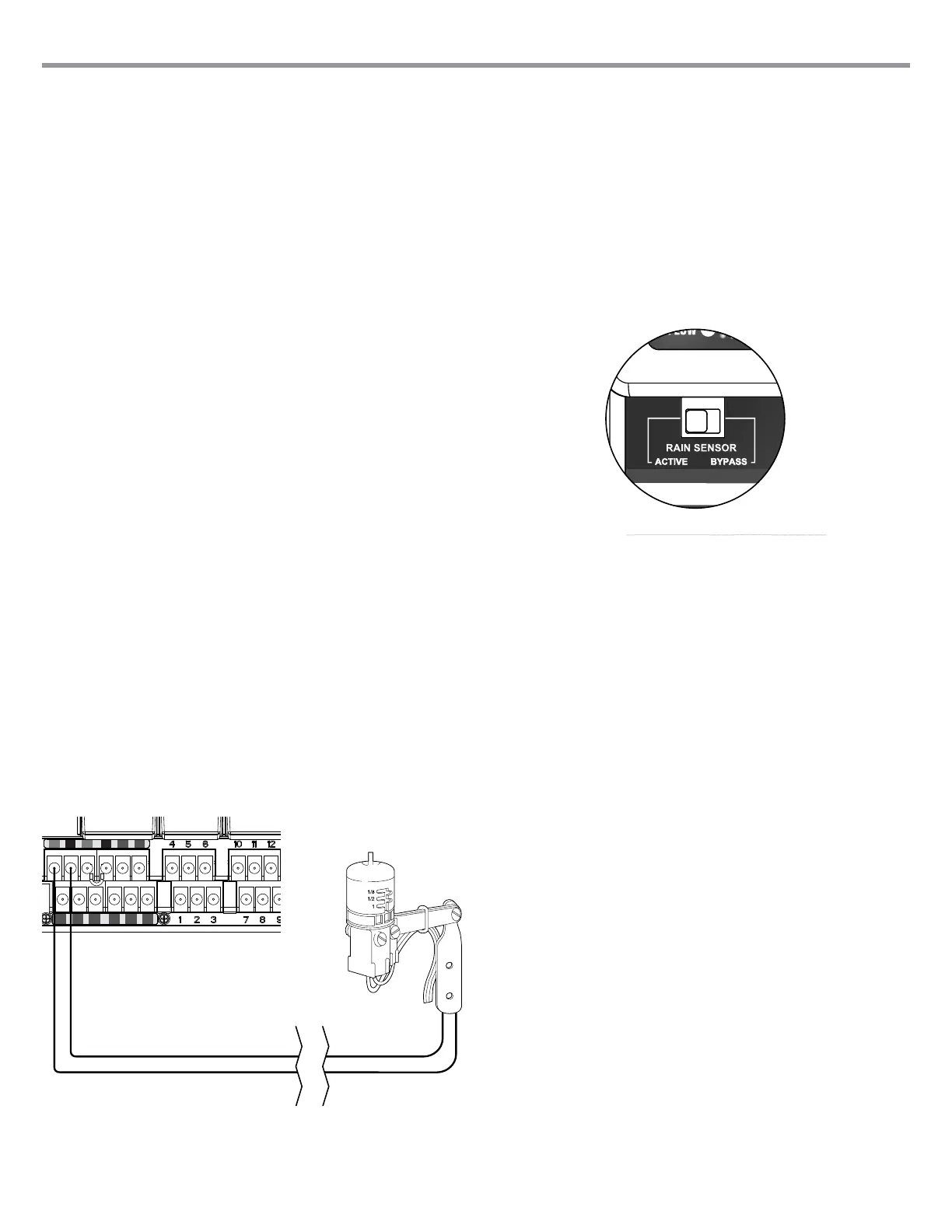
Bypassing the Sensor(s)
If the rain sensor is ACTIVE and automatic or manual operation is required,
simply move the Bypass switch to Bypass.
If the rain sensor switch is left in the ACTIVE position but no sensor is
connected and the jumper wire has been removed, the display on the
I-Core will indicate that the sensor is ACTIVE. This will also be indicated
in the System Status dashboard to the left of the display. The sensor light
will be illuminated RED for ACTIVE, thus having an open circuit. As long as
the sensor is in the ACTIVE mode, any station that has been programmed
to the ACTIVE sensor will not be allowed to water, and will be put into
Suspend mode. If you do not have a sensor and want to eliminate this
possible problem, simply keep the rain sensor switch in the bypass mode,
or install the jumper wire between the sensor terminals if it has been
removed.
Programming of the sensors will be discussed in the Set Sensor Operation
section of Programming and Operation (pg. 18).
Sensor Bypass Switch
This switch will either enable or disable a Rain or Freeze sensor that has
been connected to the controller. When the switch is in the Active position,
the controller will adhere to the state of the sensor and shut down irrigation
if the sensor is in an open state. If the sensor is in a closed state, the
controller will operate as normal. If the sensor is in an open state, but you
would like your automatic irrigation to operate as normal, simply move the
switch to the Bypass position. The sensor will now be overridden and the
controller will operate as programmed.
Once the Sensor Bypass Switch is in the Active position the System Status
Dashboard will acknowledge the switch is in the Active position, and the
Sensor Status light will light up. If the sensor is in an open state, the System
Status Sensor light will be Red. If the sensor is in a closed state, the System
Status Sensor light will be Green.
If you do not have a sensor installed, the position of the Rain Sensor switch
can be in either the Active or the Bypass mode. This is true as long as
the jumper wire connecting the two sensor terminals remain in place. If a
jumper wire has been removed, it will be necessary to keep the Rain Sensor
switch in the Bypass mode, otherwise no automatic irrigation will occur.
Weather Sensor
10