CONNECTING EARTH GROUND
Ground Wire
The I-Core features a ground lug, which is isolated from the primary AC power, and is used to ground incoming surges from the
communications and output valve wires.
Do NOT connect the primary AC 120/230V electrical ground wire to the
earth ground lug.
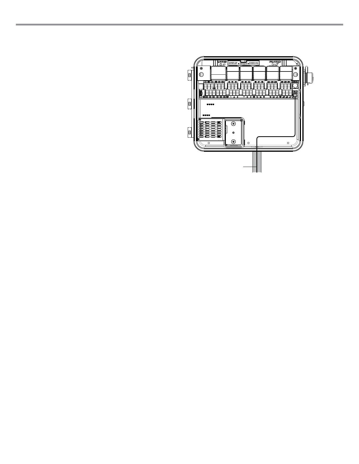
1. Use #10 (6 mm) or #8 (10 mm) bare wire to connect the controller
to the ground rod. Route the earth ground wire into the wiring
compartment through the 1 ½" conduit opening at the bottom of the
cabinet. Do not route the ground wire through the same conduit as
the incoming primary AC power.
2. Loosen the ground lug screw; insert the ground wire into the ground
lug and tighten the screw to secure the ground wire. Do not over
tighten.
Acceptable grounding consists of an 8' (2.5 m) copper-clad rod or stake, or
a 4" x 96" (100 mm x 240 cm) copper plate, or both, placed in the earth at
least 8' (2.5m) away from the controller, and with the ground wire at right
angles to the communications and valve wires, if possible. Ideal grounding
resistance would be 10 Ohms or less as measured with a “megger”
or similar device. Please consult the ASIC reference for more detailed
information on proper grounding techniques.
7