112 Powermax30 XP Service Manual 808150 Revision 0
6 – Power Supply Component Replacement
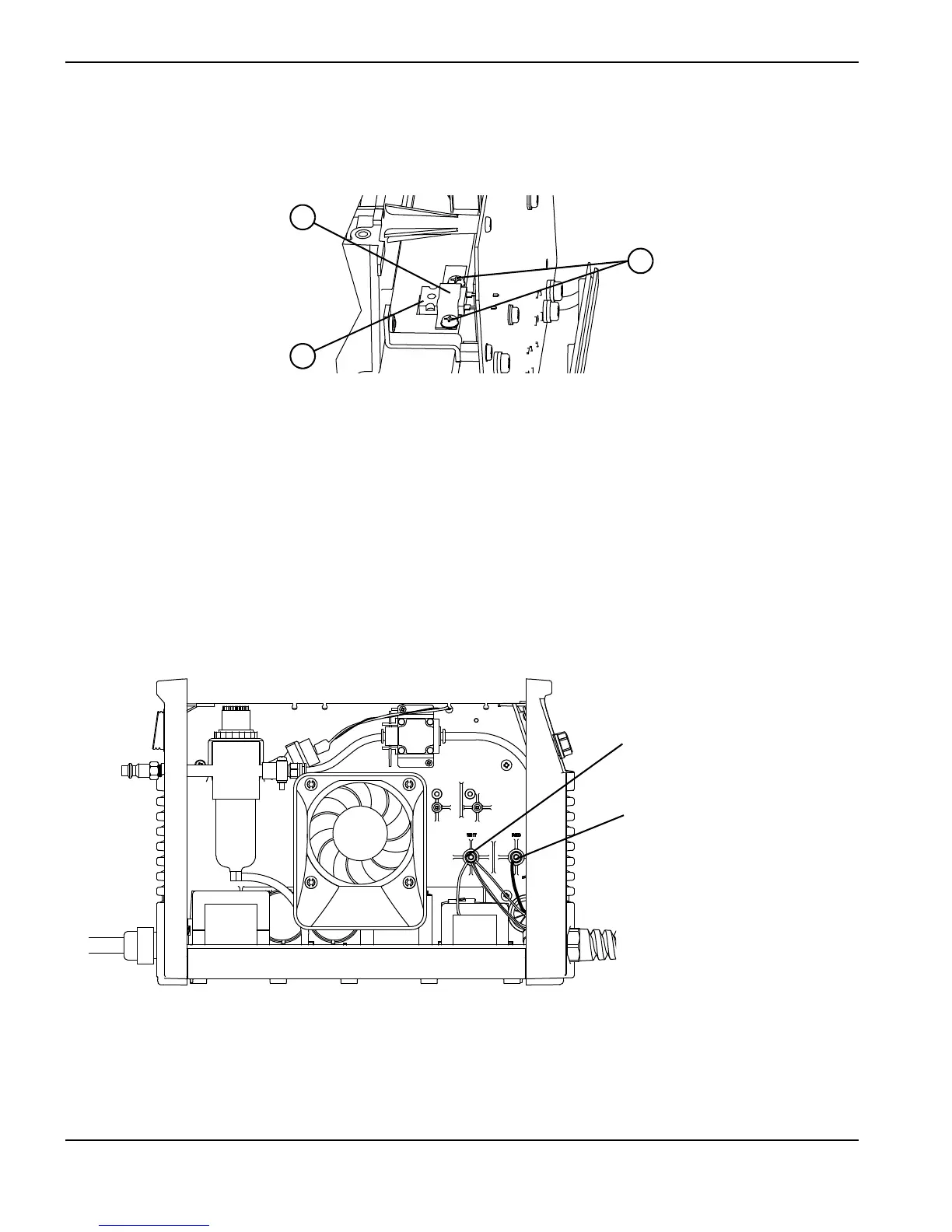
8. Remove the 2 screws from the snubber resistor spring clip on the top of the heatsink, and remove the spring clip.
Figure 49
9. Disconnect the bottom two wires (both are white) from the power switch.
10. Use an 8 mm (5/16-inch) nut driver to remove the nuts that attach the red and the white wires to the studs on the fan
side of the power supply. The studs are labeled “RED” and “WHT.”
11. Pull the red and white wires through the hole in the center panel of the power supply.
Figure 50
12. From the power board side of the power supply, push the wires that you disconnected down and out of the way.
13. Pull the board straight out from the power supply and set it aside.
1
Spring clip
2
Snubber resistor
3
Snubber resistor screws