Powermax30 XP Service Manual 808150 Revision 0 111
6 – Power Supply Component Replacement
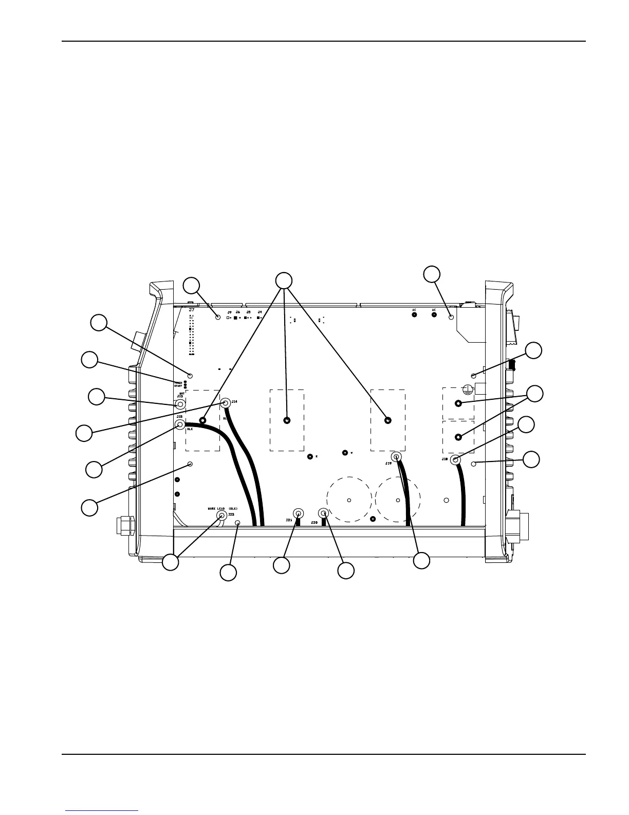
4. On the back of the power board, remove the wire connectors for the transformers and inductors. (See Figure 48.)
a. Remove J13, J14, and J15, located on the front panel end of the power board.
b. Remove J18 and J19, located on the rear panel end of the power board.
c. Remove J20 and J21, located on the bottom center of the power board.
5. Remove the work lead ring terminal from J22.
6. Remove the 3 retaining screws and the 4 heatsink assembly screws.
7. Remove the 3 screws that attach the IGBTs to the heatsink and the 2 screws that attach the input diode bridges to
the heatsink. Holes in the power board provide access to the 2 input diode bridge screws.
Figure 48
WORK LEAD (BLK)
BLK
BLK
TORCH
START
AC AC
R
w
1
Retaining screws (3)
2
Heatsink assembly screws (4)
3
Connector TORCH START (J12)
4
J13
5
J14
6
J15
7
Work lead connector (J22)
8
J21
9
J20
10
J19
11
J18
12
Input diode bridge screws (2)
13
IGBT screws (3)