A
.
INSTALLATION MANUAL
FOR ELECTRICAL PARTS
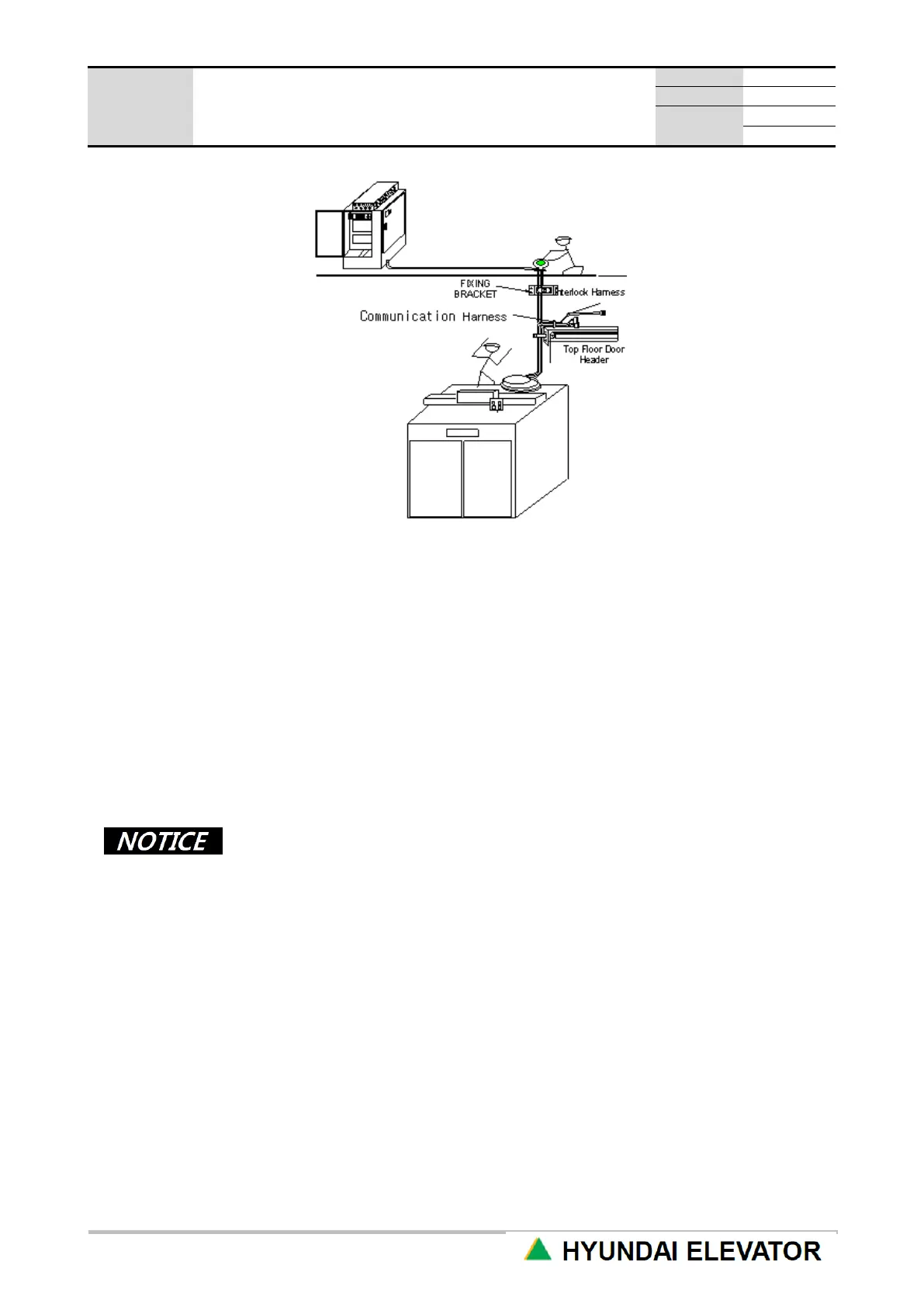
[Figure 4.2 Communication, Interlock Harness Cable]
⑪ Pull down the cable by lowering the CAR to the location where the work at the highest floor hanger
case part is easy.
⑫ Use the cable tie to firmly tie the cable harness to the hanger case. At this time, place the cable
branching point at the top of the hanger case.
⑬ Fix the remaining cable at the top of the hanger case if the cable is long.
⑭ Connect the connector of interlock cable and the connector taken out from the highest floor interlock
together at the branching point.
⑮ Check if the internal pin is projected straight up during the connector connection,
If it is bent, or if there is a curved part, be careful for the case of no connection due to the bending.
⑯ HIP and HPI have different indicator button cable connections.
• The hall button is included inside HIP, so connect the button cable to CH2 of HIP
board inside HIP itself, and connect the communication line to CH1 connector.
• The grounding connector included in the communication line should be locked by
the bottom part HIP fixing bolt.
• HPI has a separate hall button, and has the material prepared for the cable (CH2
connector) from HPI to the hall button to be taken out from HPI itself, so insert this
according to the connector of the UP/DN call button through the hall button box.
• Connect the communication line to CH1 connector. Lock the grounding connector
with the grounding bolt inside HPI box.
• Connect CN_13 and CN_A2 connectors to CH1 connector of the highest floor
HIP(HPI), and connect the end resistor to the lowest floor HIP(HPI) CH4
connector. (Installed in factory)
• When end-resistor is not installed or installed not properly, cause a CAN
communication failure.
 Loading...