142
Teaching pendant
[CON-T, RCM-T]
PC software
(Optional)
RS232C cross cable
(Provided by the user)
Components:
SIO converter (with built-in terminal resistor)
<RCB-TU-SIO-A> Vertical type
<RCB-TU-SIO-B> Horizontal type
Input power
supply
Controller power supply
Terminal resistor
R = 220
ADRS switch: 0
Controller 1
ADRS switch: 1
Controller 2
ADRS switch: n-1
Controller n
E-Con connector (AMP 4-1473562-4: housing color green)
E-Con connector (AMP 3-1473562-4: housing color orange)
Junction (AMP 5-1473574-4)
Green Green Green
(Note) External equipment communication
cable <CB-RCA-SIO-***> cannot be
used for connection to a PC.
RS232C type <RCM-101-MW>
USB type <RCM-101-USB>
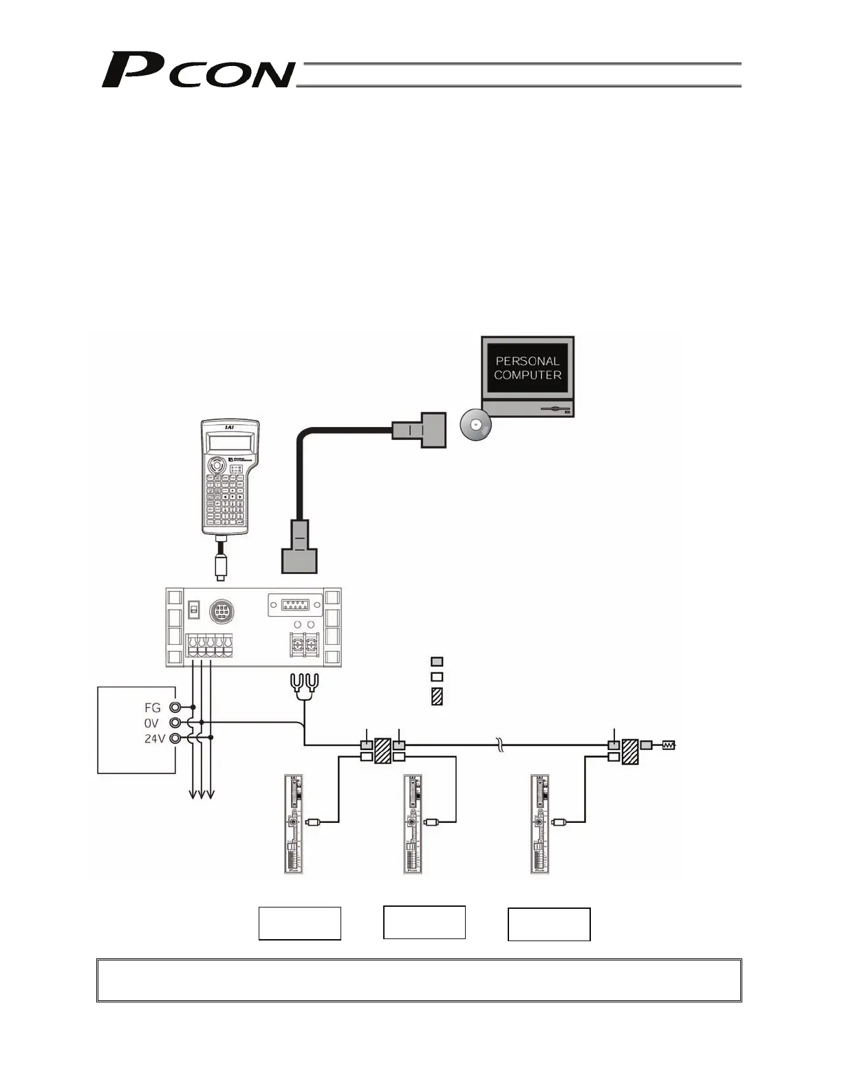
9. PC/Teaching Pendant Connection Method in Multi-axis Configurations
This section explains the method to permanently connect a PC/teaching pendant in configurations
consisting of multiple axes, so that the PC/teaching pendant connector need not be removed/inserted
each time.
The connector is connected to a SIO converter, and the SIO converter sends/receives data to/from each
controller via RS485 serial communication.
The basic specifications are as follow:
[1] Maximum number of connected axes: 16
[2] Maximum length of serial communication cable: 100 m or less
[3] Terminal resistor: 220 (Be sure to install a terminal resistor for the last axis to prevent the effect
of radiating noise.)
9.1 Connection Example
Caution: Do not connect the teaching pendant and PC at the same time.
If both are connected at the same time, a communication error (message level) will occur.
Controller link cable
<CB-RCB-CTL002>