48
5.3 Details of I/O Signal Functions
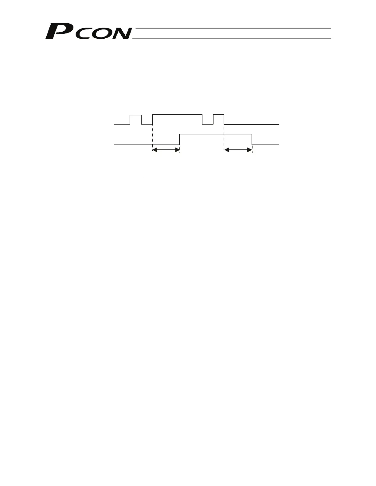
An input time constant is provided for the input signals of this controller, in order to prevent malfunction
due to chattering, noise, etc.
Except for certain signals, switching of each input signal will be effected when the signal has been
received continuously for at least 6 msec. For example, when an input is switched from OFF to ON, the
controller will only recognize that the input signal is ON after 6 msec. The same applies to switching of
input signals from ON to OFF (Fig. 1).
Fig. 1 Recognition of Input Signal
5.3.1. Details of Each Input Signal
Operating mode (RMOD)
This controller has a mode selector switch on the front panel of the controller to prevent malfunction and
data loss due to duplicate operations.
Normally this switch should be set to the “AUTO” position when the actuator is operated in the auto mode
using I/O signals exchanged with a PLC, or to the “MANU” position when the actuator is operated
manually using a PC or teaching pendant.
If the controller is mounted in a control panel, however, this switch is not readily accessible. Accordingly, a
function has been added to allow the setting of this switch to be changed from a PLC for added
convenience.
Specifically, the internal operating mode of the controller will become “AUTO” when this signal is turned
OFF, or “MANU” when this signal is turned ON, if the mode selector switch is set to the “AUTO” position.
If the mode selector switch is set to the “MANU” position, the internal operating mode of the controller will
remain “MANU” regardless of the status of this signal.
Use this signal in applications where the operation mode must be switched frequently between auto and
manual and the selector switch is provided on the equipment side.
Start (CSTR)
Upon detecting an OFF ON rise edge of this signal, the controller will read, as a binary code, the target
position number consisting of six bits from PC1 to PC32 (or eight bits from PC1 to PC128 when the PIO
pattern is “256-point type,” or nine bits from PC1 to PC256 when the PIO pattern is “512-point type”),
and execute positioning to the target position of the corresponding position data.
Before executing this command, the target position, speed and other operation data must be set in the
position table using a PC/teaching pendant.
If a start command is issued when home return operation has not been performed yet after the power was
input (the HEND output signal is OFF), the controller will automatically perform home return operation
before positioning to the target position.
Command position number (PC1 to PC256)
When a movement command is effected upon OFF ON of the start signal, the nine-bit binary code
consisting of signals PC1 to PC256 will be read as the command position number.
In the standard or teaching type, six bits of PC1 through PC32 are used. In the 256-point type, eight bits of
PC1 to PC128 are used. In the 512-point type, nine bits of PC1 through PC256 are used.
The weight of each bit is as follows: 2
0
for PC1, 2
1
for PC2, 2
2
for PC4, …, and 2
9
for PC256. A desired
position number between 0 and 511 (maximum) can be specified.
6 [msec] 6 [msec]
Input signal
Recognition by controller
Not recognized
Not recognized