40
5.2 PIO Patterns and Signal Assignments
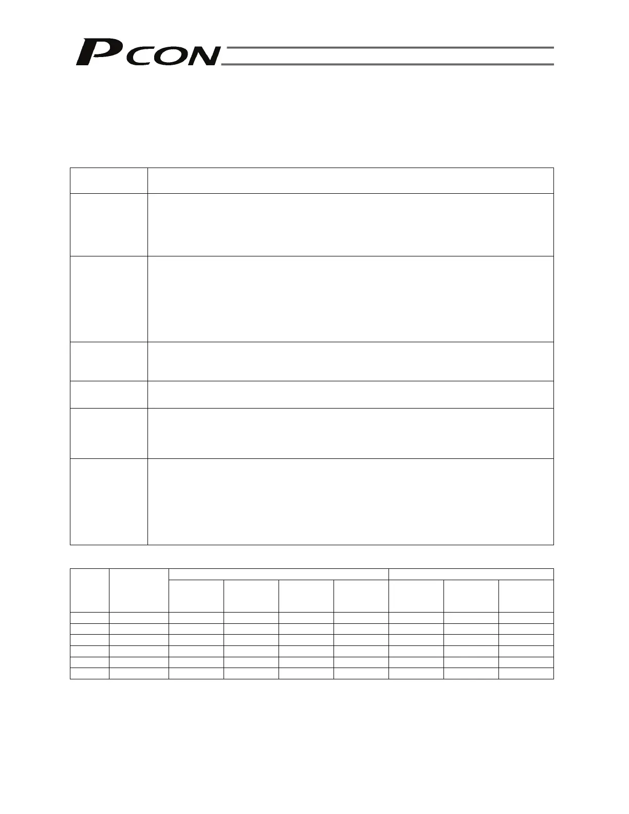
This controller provides six PIO pattern types to meet the needs of various applications.
To select a desired type, set a corresponding value from 0 to 5 in parameter No. 25 (PIO pattern
selection).
The features of each PIO pattern are explained below:
Parameter No.
25 setting
Feature of PIO pattern
0
Positioning mode (Standard type)
A basic type supporting 64 positioning points and two zone outputs.
* How to set zone boundaries within which to output a zone signal:
Zone boundaries are set using parameter Nos. 1 and 2 for one zone output, and in the
position table for another zone output.
1
Teaching mode (Teaching type)
In this type, 64 positioning points and one zone output (boundaries are set in the
position table) are supported.
In addition to the normal positioning mode, the user can also select the teaching mode
in which the actuator can be jogged via I/Os and the current actuator position can be
written to a specified position.
(Note) Positions can be rewritten by approximately 100,000 times.
2
256-point mode (256-point positioning type)
The number of positioning points is increased to 256, so only one zone output is
available (boundaries are set in the position table).
3
512-point mod (512-point positioning)
The number of positioning points is increased to 512, so no zone output is available.
4
Solenoid valve mode 1 (7-point type)
The number of positioning points is limited to seven to offer separate direct command
inputs and movement complete outputs.
PLC ladder sequence circuits can be designed easily.
5
Solenoid valve mode 2 (3-point type)
Use of the controller as an air cylinder is assumed in this type.
Movement complete output signals function differently in this type, compared to the 7-
point type.
Specifically, the signal functions not only to “indicate movement complete,” but also to
“detect a position” in the same manner as auto-switches of an air cylinder. Push & hold
operation cannot be performed.
Quick reference table for functions available under each PIO pattern (: Available, X: Not available)
Input signals Output signals
No. 25
Number of
positioning
points
Brake
release
Home
return
Jog
Current-
position
write
Zone
Position
zone
Ready
0 64 points
x x
1 64 points x
x
2 256 points
x x x
x
3 512 points
x x x x x
4 7 points
x x
x
5 3 points
x x x
x
(Note) For “Zone” and “Position zone,” different methods are used to set boundaries defining the range
within which the zone signal will turn ON.
“Zone” is set by parameter Nos. 1 and 2, and thus its setting will become effective after home
return is completed.
“Position zone” is set in the “Zone+” and “Zone-“ fields for each position number in the position
table, and thus its setting will become effective after a movement command is input.