84
7. Operation <Practical Steps>
7.1 How to Start
7.1.1 Timings after Power On
Procedure after initial startup until actuator adjustment
[1] Connect the motor relay cable to the MOT connector and encoder relay connector to the PG
connector.
[2] Connect the supplied flat cable to the PIO connector (for connection between the host PLC and I/O
unit).
[3] Reset the emergency stop or enable the supply of motor drive power.
[4] Supply the 24-VDC I/O power (1A/2A pins (+24 V) and 19B/20B pins (0 V) in the PIO connector).
[5] Supply the 24-VDC controller power (24-V and 0-V terminals on the power-supply terminal block).
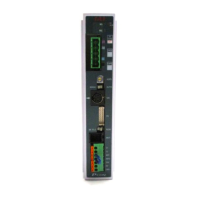
* If the monitor LED [SV/ALM] on the front panel illuminates for 2 seconds initially and then turns off,
the controller is normal. If [SV/ALM] illuminates in red, an alarm is present. In this case, connect a
PC or teaching pendant to check the nature of the alarm and remove the cause by referring to
Chapter 10, “Troubleshooting.”
[6] Set the minimum set of required parameters initially.
Set the mode selector switch on the front panel to the “MANU” side.
On the PC or teaching pendant, set the MANU operation mode to “Teaching mode: Enable safety
speed].
Change the necessary parameters in this condition.
(Example) Use a PIO pattern other than “Standard type” Parameter No. 25 (PIO pattern
selection)
Reduce the safety jog speed Parameter No. 35 (Safety speed)
[7] Check the actuator position.
Confirm that the slider or rod is not contacting a mechanical end.
If the slider/rod is contacting a mechanical end, move it away from the mechanical end. If the
slider/rod is not contacting a mechanical end but is closer to the home position, move the slider/rod
away from the home position.
If the actuator is equipped with a brake, turn on the brake forced-release switch to forcibly release the
brake before moving the actuator.
The slider/rod may suddenly drop due to its dead weight when the brake is released, so exercise
caution not to damage the robot hand or load by the falling slider/rod.
If the actuator cannot be moved by hand because the screw lead is short, change the setting of
parameter No. 28 (Default direction of excited-phase signal detection) to the direction opposite to the
mechanical end.
Warning
If the servo is turned ON while the slider/rod is contacting the mechanical end, excitation
phase detection may not be performed correctly and an abnormal operation or excitation
detection error may result.
[8] Turn on the servo.
Turn on the servo using the “servo ON function” of the PC software or teaching pendant.
If the actuator enters a servo lock mode and the monitor LED [SV/ALM] on the front panel illuminates
in green, the controller is functioning properly.
[9] Check the operation of the safety circuit.
Confirm that the emergency stop circuit (or motor drive-power cutoff circuit) operates properly.

 Loading...