17
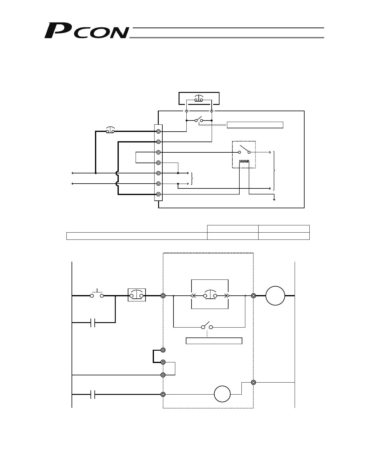
(2) Wiring the emergency-stop switch
In many cases multiple controllers are used in a single system.
To provide an emergency-stop function for the entire system, the controller circuit is designed in such a
way that a single EMG switch is able to actuate an emergency stop in all connected controllers.
[Internal emergency-stop circuit]
(Note) The current consumption of the internal relay is 10 mA or less.
(Reference) Cutoff voltage Cutoff current
EMG switch on teaching pendant 30 VDC 3 A
[Example of recommended circuit]
(Note) To cut off the motor drive power supply in conformance with safety category 2, connect 24V to the
EMG terminal and a contactor or other contact device to the MPI/MPO terminals. (Refer to 4.2.3;
rush current: 8 A.)
24V
0V
0V
EMG-
24V
MPO
MPI
S1
S2
0V
Teaching pendant
Relay
Motor power
supply
Input power supply
(2 A max.)
EMG signal
Controller power
supply
PCON-C controller
Connection detection circuit
0V
0V
CR
(3A)
S2S1
CR
CR
24V
EMG-
24V
MPO
MP1
External EMG
reset switch
External EMG circuit
EMG switch on
teaching pendant
Relay
PCON-C controller
Coil current:
0.1 A or less
Connection detection circuit