23
Controller
I/O flat cable
0 V (NPN
specification)
24 V (PNP
specification)
24 V (NPN
specification)
0 V (PNP
specification)
24-VDC power for
input/output signals
For details on I/O signal connection, refer to
4.3, “Connecting the I/O Cables.”
Connection
Input
Output
Motor relay cable
Encoder relay cable
Yellow
Blue
Orange
Pink
Purple
Green
Brown
Gray
Red
Connected to teaching
pendant or PC
Input power
supply 24
VDC
Motor drive-
power cutoff
circuit
Actuator
Motor
Encoder
Holding brake
Brake release switch
Terminal block
Orange
Gray
White
Yellow
Pink
Yellow (Green)
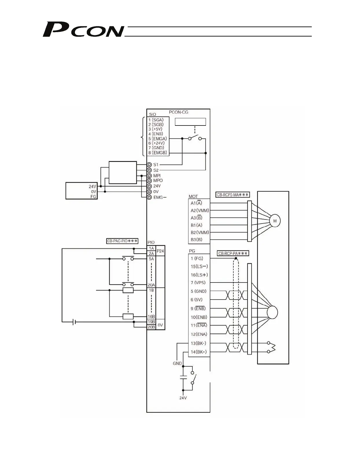
4.2 External Drive-Power Cutoff Relay Type (PCON-CG)
4.2.1 External Connection Diagram
An example of standard wiring is shown below.
(Note) The encoder cable shown in the example is the standard cable.
As for the robot cable, refer to 4.4.1 as the color of the cable is different.