36
Controller end
Actuator end
Pin layout
Pin layout
(Front view)
Cable model marking
Cable colo
Signal name
Pin No.
Pin No.
(Front view)
Housing: 1-1318119-3 (AMP)
Contact: 1318107-1
Housing: SLP-06V (J.S.T. Mfg.)
Socket contact: BSF-21T-P1.4
Orange
Gray
Yellow
Yellow
(Green)
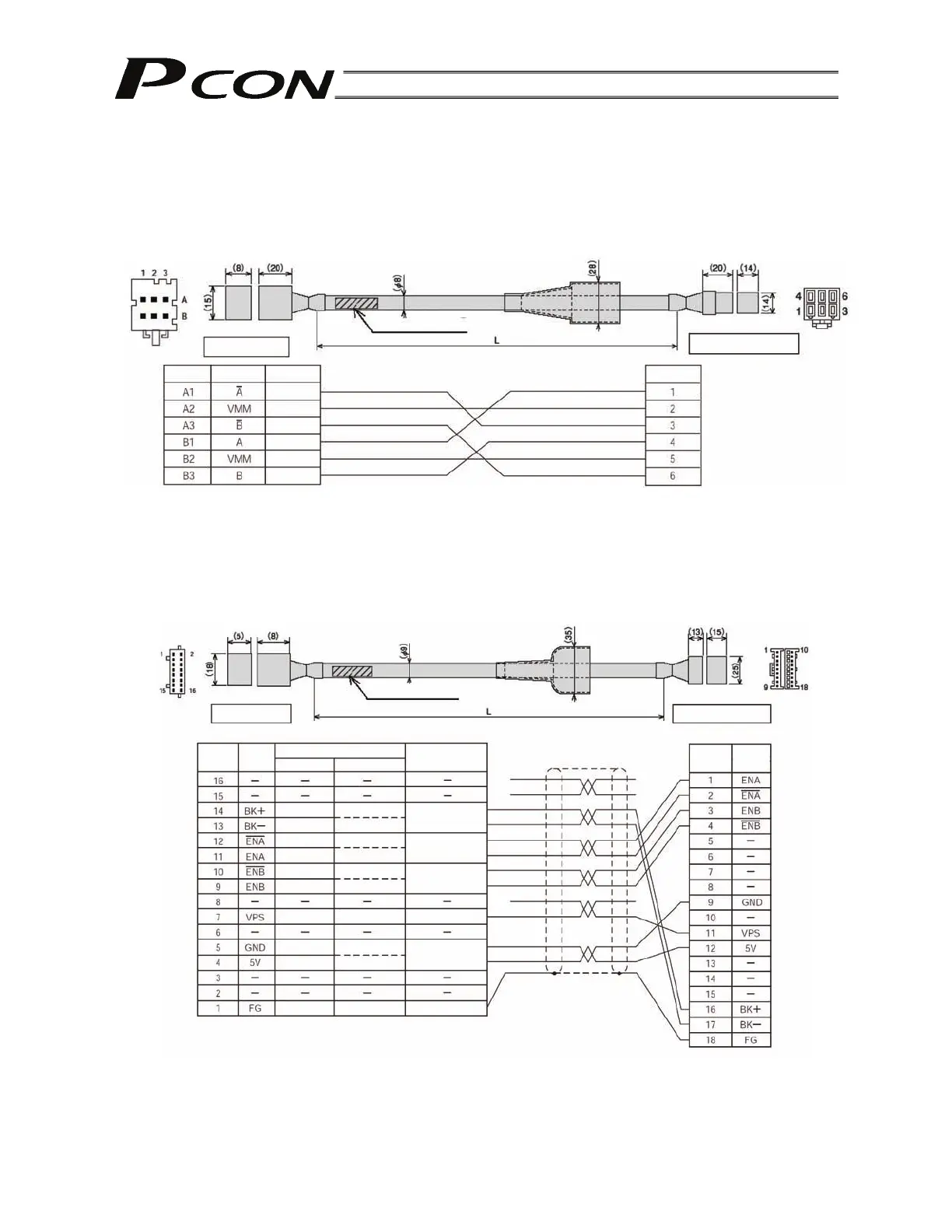
4.4.2 Connecting the PCON-CF and Actuator
Use dedicated relay cables to wire the controller and actuator.
(1) RCP2 motor cable
Model: CB-RCP2-MA
( indicates the cable length L. Example. 080 = 8 m)
(2) RCP2 encoder cable/encoder robot cable (dedicated cable for PCON-CF)
Model for standard cable: CB-RFA-PA
Model for robot cable: CB-RF-PA -RB (optional)
( indicates the cable length L. Example. 080 = 8 m)
White
Pink
Controller end
Actuator end
Pin layout
Pin layout
(Front view)
Cable model marking
(Front view)
Red
Gray
Brown
Green
Purple
Pink
Yellow
Blue
Orange
Ground
Brake power
Encoder phase
A signal
Encoder phase
B signal
Encoder control signal
Encoder
owe
Shield
Ground
Purple
White
Blue
White
Yellow
White
Green
White
Red
Cable colo
Signal
name
Pin No.
Robot cable
Standard cable
Descri
tion
Pin No.
Signal
name
Housing: PHDR-16VS (J.S.T. Mfg.)
Contact: SPHD-001T-P0.5
Housing: XMP-18V (J.S.T. Mfg.)
Contact: BXA-001T-P0.6
Retainer: XMS-09V