145
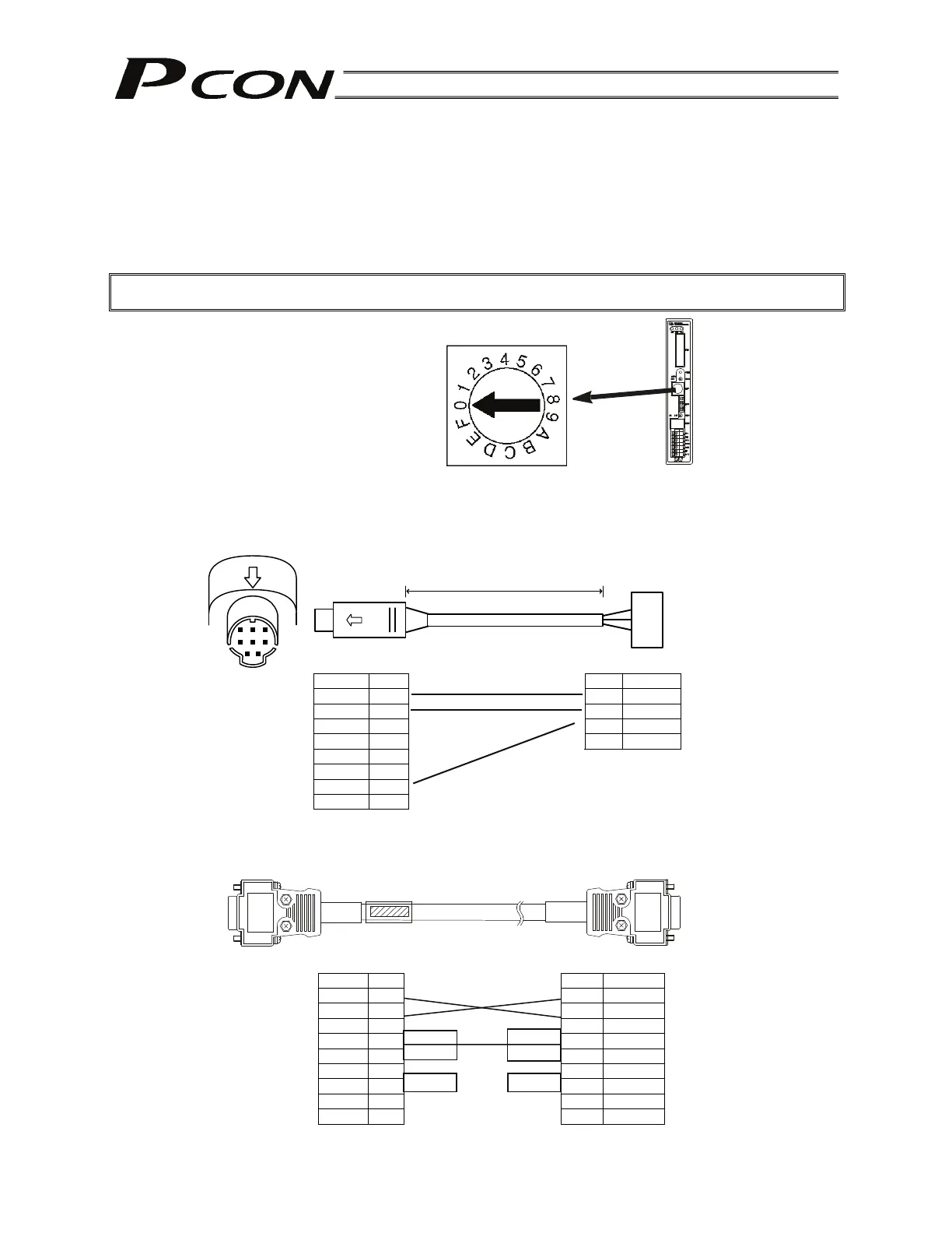
9.3 Address Switch
Set an address (0 to 15) as a hexadecimal (0 to F) using the ADRS switch on the front panel of each
controller to define the slave number for the controller.
Assign “0” to the controller nearest the host, and then assign 1, 2, 3, …, E and F to the remaining
controllers in the direction of moving away from the host.
After all addresses have been set, reconnect the power.
Caution: After the setting, be sure to confirm that the addresses are not duplicated.
9.4 Connection Cables
Controller link cable
Model: CB-RCB-CTL002
(Reference) Connection diagram for RS232C cross cable
SIO converter end PC end
Signal No. No. Signal
SGA 1 1 SGA
SGB 2 2 SGB
+5V 3 3 GND
EMB 4 4
EMGA 5
+24V 6
GND 7
EMGB 8
Signal No.
1
RD 2
SD 3
ER 4
SG 5
DR 6
RS 7
CS 8
9
No. Signal
1
2 RXD
3 TXD
4 DTR
5 SG
6 DSR
7 RTS
8 CTS
9
Controller end
200 mm
Mini DIN connector
E-Con connector
3-1473562-4
(Housing color: Orange)
Yellow
Orange
Blue
Adjust the arrow to a desired
position using a flathead
screwdriver.
D-sub, 9-pin female connector
D-sub, 9-pin
(Female connector for PC,
Male connector for PLC)
1 2
3 5
6 8

 Loading...


