25
24V
0V
0V
EMG-
24V
MPO
MPI
S1
S2
(3A)
EMG switch
(Rush-in current: 8 A,
rated current: 2 A)
Teaching pendant
Motor power
supply
External EMG
reset switch
External EMG
circuit
Controller power
supply
Coil current: 0.1 A or less
(MAX. 2A)
PCON-CG controller
Connection
detection circuit
MC
MC
MC
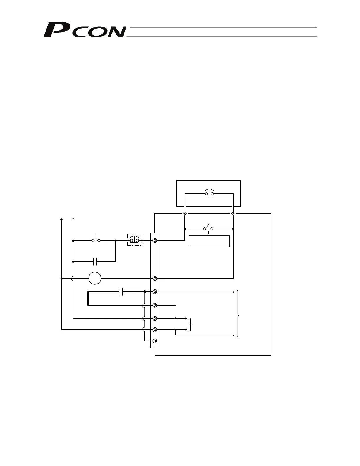
(2) Wiring the motor power cutoff relay
Explained below is a safety circuit conforming to safety category 2.
The user is responsible for implementing additional safety measures in the actual circuit configuration,
such as providing double contactor contacts to prevent fusing.
The circuit illustrated below is for reference purposes only.
The input side of the motor drive power supply is connected to the MPI terminal, while the output side
is connected to the MPO terminal. Connect a contactor or other contact device to these terminals.
(Note) The rush current must be 8 A or less. The rated current is 2 A.
The contact for the EMG switch on the teaching pendant is provided by the S1/S2 terminals.
(Note) When connecting the teaching pendant to a SIO converter, the contact for the EMG switch on the
teaching pendant is provided by the EMG1/EMG2 terminals on the SIO converter.
[Example of basic circuit]