47
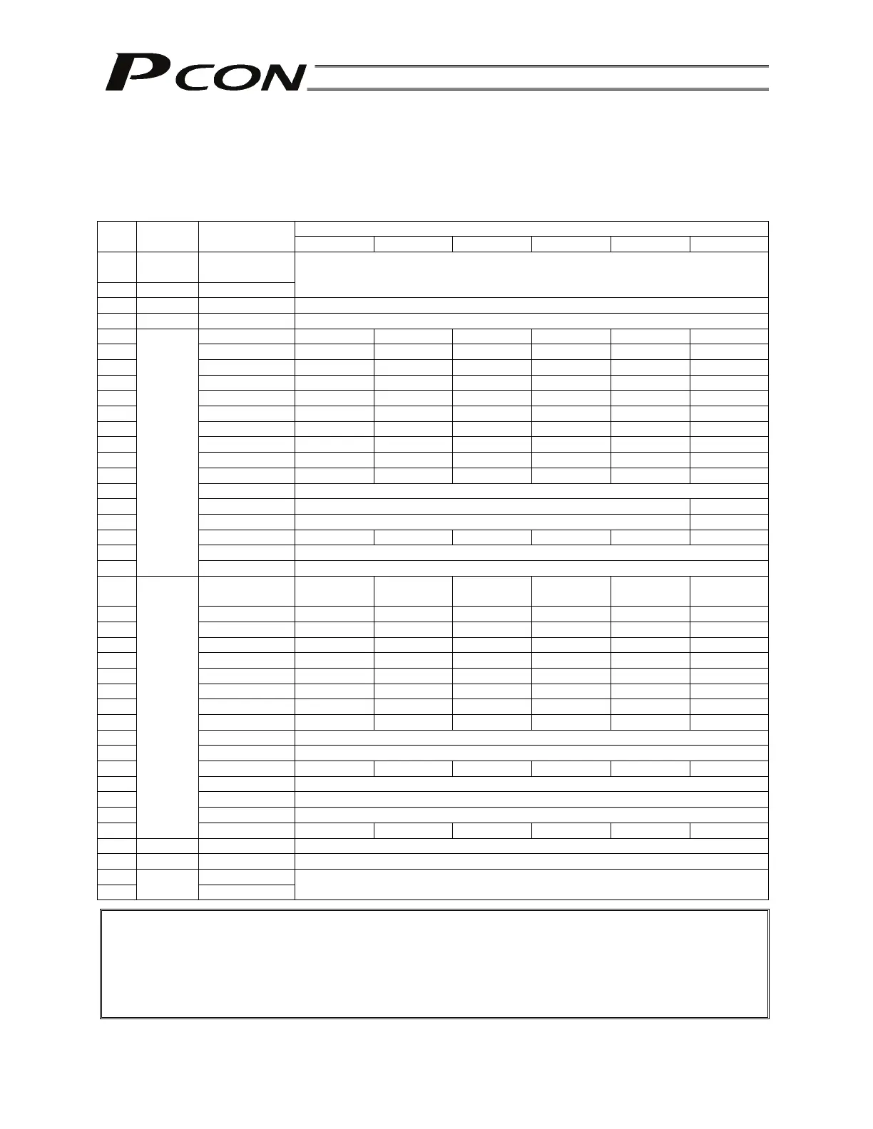
5.2.2 Signal Assignment Table for Respective PIO Patterns
When creating a PLC sequence or wiring signals, assign each pin correctly by referring to the assignment
table below.
When “1 [Teaching type]” is selected, the meaning of each pin number will vary depending on the mode.
Accordingly, also pay due attention to the mode switch timings.
Parameter No. 25 setting Pin
No.
Category Wire color
0 1 2 3 4 5
1A
+24V
Upper stage
Brown - 1
2A Red - 1
P24
3A Orange - 1 (Not used)
4A Yellow - 1 (Not used)
5A Green - 1 PC1 PC1 PC1 PC1 ST0 ST0
6A Blue - 1 PC2 PC2 PC2 PC2 ST1 ST1 (JOG+)
7A Purple - 1 PC4 PC4 PC4 PC4 ST2 ST2 (-)
8A Gray - 1 PC8 PC8 PC8 PC8 ST3 -
9A White - 1 PC16 PC16 PC16 PC16 ST4 -
10A Black - 1 PC32 PC32 PC32 PC32 ST5 -
11A Brown - 2 - MODE PC64 PC64 ST6 -
12A Red - 2 - JISE PC128 PC128 - -
13A Orange - 2 - JOG+ - PC256 - -
14A Yellow - 2 BKRL JOG- BKRL BKRL BKRL BKRL
15A Green - 2 RMOD
16A Blue - 2 HOME -
17A Purple - 2 *STP -
18A Gray - 2 CSTR
CSTR/PWRT
CSTR CSTR - -
19A White - 2 RES
20A
Input
Black - 2 SON
1B
Lower stage
Brown - 3
PM1 PM1 PM1 PM1 PE0 LS0
2B Red - 3 PM2 PM2 PM2 PM2 PE1 LS1 (TRQS)
3B Orange - 3 PM4 PM4 PM4 PM4 PE2 LS2 (-)
4B Yellow - 3 PM8 PM8 PM8 PM8 PE3 -
5B Green - 3 PM16 PM16 PM16 PM16 PE4 -
6B Blue - 3 PM32 PM32 PM32 PM32 PE5 -
7B Purple - 3 MOVE MOVE PM64 PM64 PE6 -
8B Gray - 3 ZONE1 MODES PM128 PM128 ZONE1 ZONE1
9B White - 3 PZONE PZONE PZONE PM256 PZONE PZONE
10B Black - 3 RMDS
11B Brown - 4 HEND
12B Red - 4 PEND PEND/WND PEND PEND PEND -
13B Orange - 4 SV
14B Yellow - 4 *EMGS
15B Green - 4 *ALM
16B
Output
Blue - 4
LOAD/TRQS
-
LOAD/TRQS LOAD/TRQS LOAD/TRQS
-
17B Purple -4 (Not used)
18B Gray - 4 (Not used)
19B White - 4
20B
0V
Black - 4
0V
Caution: [1] The signals indicated by * in the table (*ALM, *STP and *EMGS) are based on the
negative logic, meaning that they remain ON in normal conditions of use.
[2] Do not connect pins denoted by “Not used” (orange-1, yellow-1, blue-4, purple-4, gray-
4), but insulate them instead.
[3] The NPN and PNP specifications use the same power line configuration, so there is no
need to reverse the power signal assignments for a PNP controller.
( ) indicates signals before home return.