61
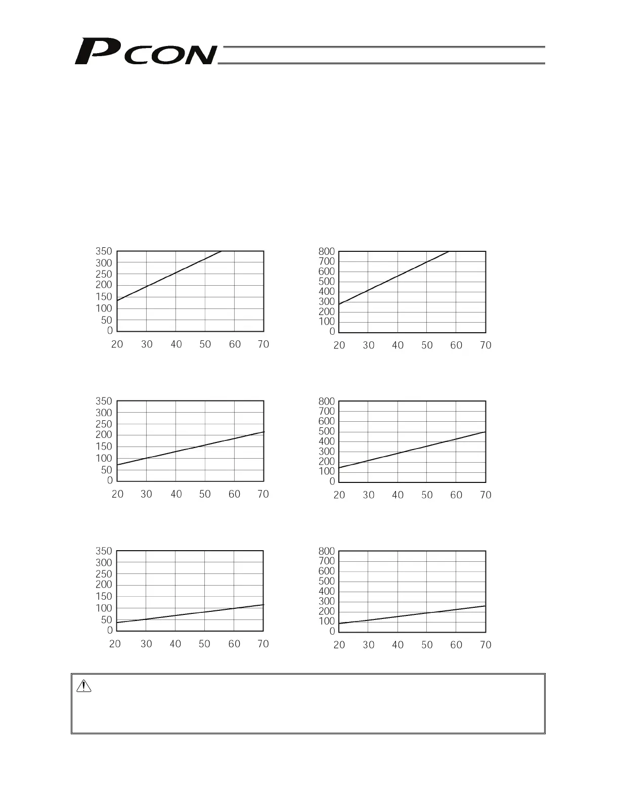
6.1.1 Relationship of Push Force at Standstill and Current-Limiting Value
When performing operation in the push & hold mode, enter the current-limiting value (%) in the push
column of the position-data table.
Determine the current-limiting value (%) from the push force to be applied to the load at standstill.
The graphs below illustrate the relationship of push force at standstill and current-limiting value for each
actuator type:
Note: For information on the RCP3, check the operation manual for the RCP3.
Slider type
(1) SA5C/SA6C/SS7C type (2) SA7C type
Caution: The precision of push force at standstill is not guaranteed. The above graphs are provided
for reference purposes only. If the push force is too small, malfunction may occur during
push & hold operation due to slide resistance, etc., so exercise caution.
The maximum current-limiting value is shown in the above graphs. The minimum value is 20%.
Current-limiting value (%)
Push force (N)
Low-speed type
(Lead: 4 mm)
Low-speed type
(Lead: 3 mm)
Push force (N)
Current-limiting value (%)
Current-limiting value (%)
Push force (N)
Medium-speed type
(Lead: 8 mm)
Medium-speed type
(Lead: 6 mm)
Push force (N)
Current-limiting value (%)
Current-limiting value (%)
Push force (N)
High-speed type
(Lead: 16 mm)
High-speed type
(Lead: 12 mm)
Current-limiting value (%)
Push force (N)