334
Part 4 CommandsChapter 6 Application Program Examples
Part 4 Commands
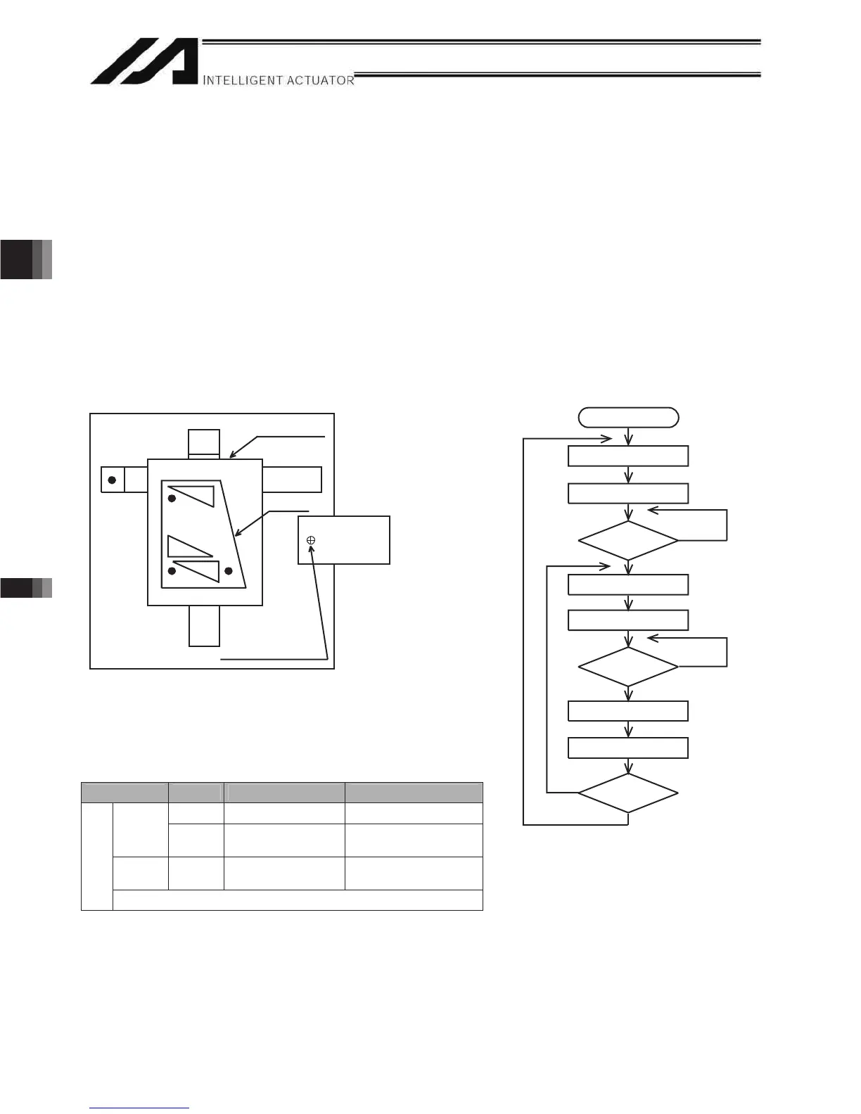
(2) Explanation of the operation
1. The XY-table moves to the operation home (P1) and waits.
2. The operator sets a load on the XY-table and turns on the start switch.
3. The XY-table moves to riveting position No. 1 (P2) on the work part and a riveting command is output
to the riveter.
4. When the riveter completes the riveting operation and a completion signal is input, the table will
move to riveting position No. 2 (P3) and then No. 3 (P4), in the same manner.
5. When all three points have been riveted, the table will return to the operation home (P1).
The above operation will be repeated. The operation position, external I/O assignments and operation
flow chart of this operation are shown below:
Operation Position
I/O Assignments
Category I/O No. Signal name Specification
16 Start command
Pushbutton switch
Input
17
Riveting
completion
Contact signal
Output 309
Riveting
command
24 VDC
XSEL
* Flag is used from 600.
Operation Flow Chart
Start
Move to position No. 1
Work part counter = 2
Start
Move to riveting position
Riveting command ON
Riveting
complete
Riveting command OFF
Work part counter + 1
Operation
complete
N
N
P1
(Operation
home)
Riveter position
Work part
XY-table
Y
Y
N
P3 P2
P4

 Loading...


