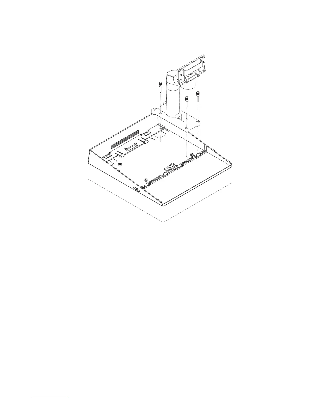
5. Place the arm assembly on the stiffening plate as shown in Figure 36. Insert
and tighten the three thumb screws as shown.
Note: The left or right placement of the arm assembly depends upon your
configuration.
6. Attach the 4820 to the pedestal.
7. Install the options. (See “Installing options” on page 43.)
Figure 36. Securing the arm assembly to the 4694
Integrated touch pedestal instructions
Update November 2005
Chapter 2. Installing the IBM 4820 37
|
|
|
|
|
|
|
|
|