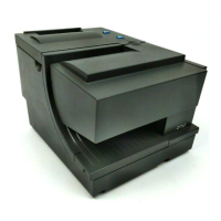
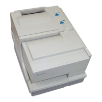
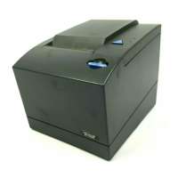
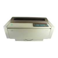
Switch Assembly, Cover Open
245
Switch Assembly, Cover Open
Removal
1. Prepare the printer for maintenance (page 152).
2. Remove the shuttle cover assembly (page 203).
3. Carefully lift and pry the cover open switch assembly out of its well in the
base casting to the right of the shuttle motor. (See Figure 47, page 264,
item 18.)
4. Trace the cover open switch cable back to the controller board, releasing
the cable from the restraints under the base casting. (See cable routing
diagrams on page 300 and page 302.)
5. Disconnect connector shell P107 (P7) from the controller board.
6. Trace the ribbon motor wires to the connector shell, and remove the cable
connector from the connector shell (page 195).
Installation
1. Remove the protective covering from the adhesive backing on the cover
open switch assembly.
2. Feed the switch cable down into the cover open switch well to the right of
the shuttle motor. Position the cover open switch assembly in the base
casting and press it into place. (See Figure 47, page 264, item 18.)
3. Route the cover open switch cable back to the controller board, installing
the cable in the restraints under the base casting. (See cable routing
diagrams on page 300 and page 302.)
4. Connect the cover open cable to the connector shell (page 195), then
connect the connector shell P107 (P7) to the controller board.
5. Install the shuttle cover assembly (page 203).
6. Return the printer to normal operation (page 153).
 Loading...


