343
b. Make sure the restraining cable is attached and unbroken.
c. Make sure there are no exposed or sharp edges.
d. Open the rear cabinet door and inspect the lower rear paper path:
e. Make sure the service panel permitting access to the I/O plate and
circuit breaker (on/off switch) is installed.
f. Make sure the paper stacker tray assembly or optional power stacker
is in place and undamaged.
Print Mechanism
1. Open the printer top cover.
2. Make sure the shuttle cover is correctly installed and undamaged. (See
page 203.)
3. Make sure the paper guide assembly is correctly installed and
undamaged. (See page 229.)
Inspect Electrical Parts
Safety Ground Path
1. Make sure the printer power cord is unplugged.
2. Remove the paper guide assembly (page 229).
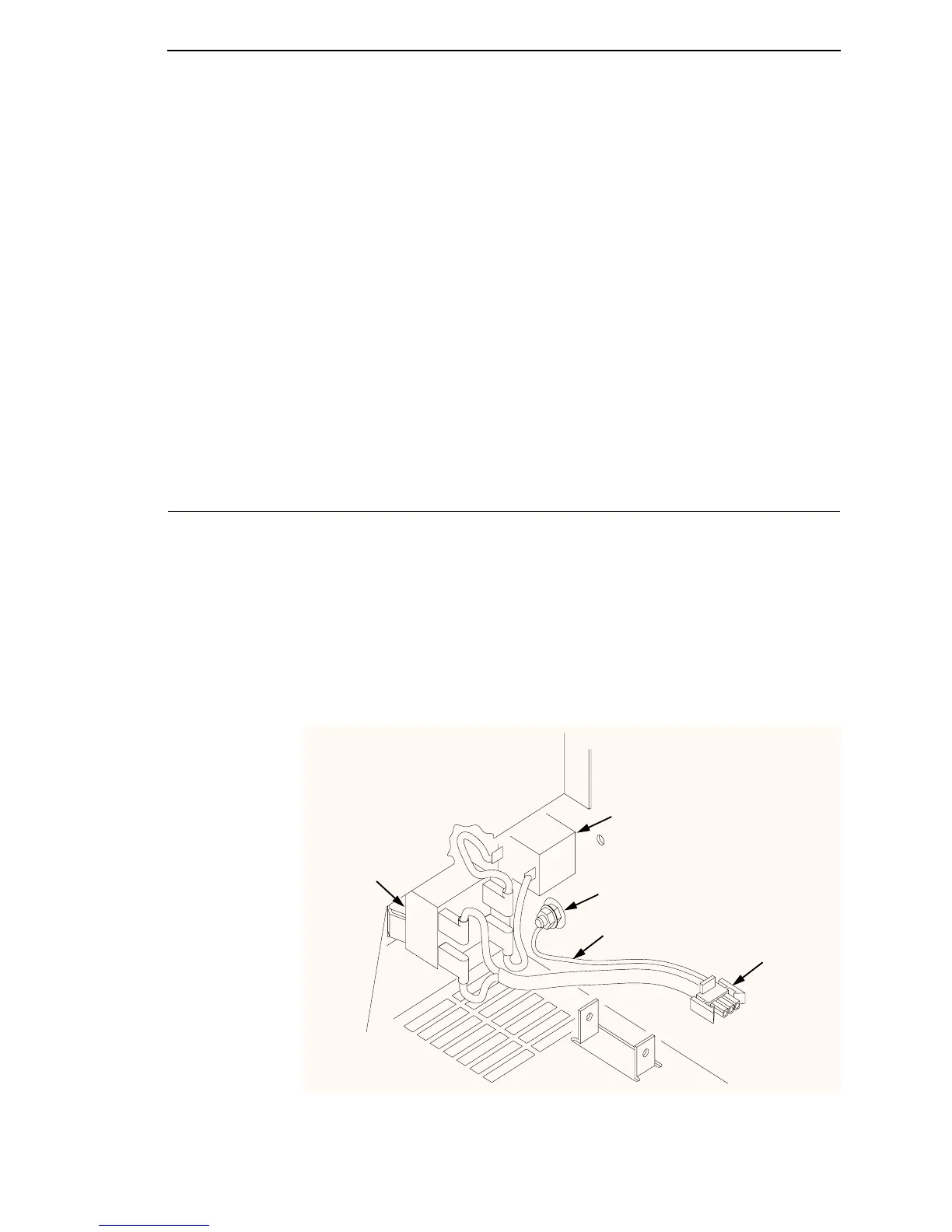
3. Make sure the ground cable from the circuit breaker power leads is
undamaged and firmly attached to the ground lug on the wall of the card
cage, as shown in Figure 56.
NOTE: Ground paths for the entire printer are summarized in Figure 57.
Figure 56. Circuit Breaker Ground, Cabinet Models
Ground Lug
NOTE: The card cage fan
and power supply board are
removed here for clarity.
Ground Cable
(To Power
Supply J1)
IEC 320 AC Power
Connector (J301)
Circuit
Breaker

 Loading...


