344
Appendix E Inspect Electrical Parts
4. Set a Fluke meter (P/N 8496278) or similar device to the lowest
resistance scale. Measure the resistance between the power cable
ground pin and the printer frame: safety ground circuits should measure
0.1 Ohm or less.
5. Install the paper guide assembly (page 229).
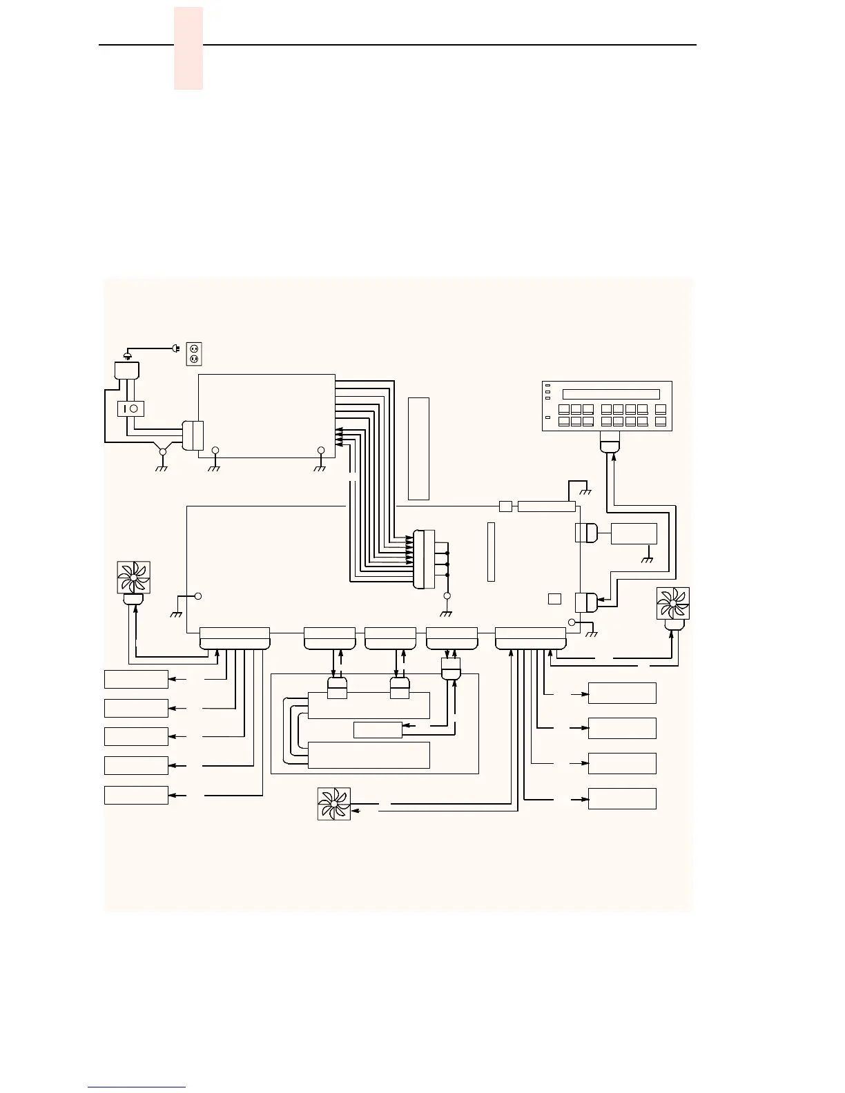
Figure 57. Ground Path Diagram
OPERATOR PANEL
+5 V
AC
POWER
Parallel
I/O
P
112
J
1
1
2
SHIELD
GND
J
3
1
0
P310
J301
CIRCUIT
BREAKER
IEC 320
AC POWER
P
1
J
1
AC
AC to DC
Power Supply
Board
Line 1
Line 2 / Neutral
CHASSIS
GND
J108 HBL
P108 HBL
J105 HBP
P105 HBP
J116 SMD
P116 SMD
J107 MSR
P107 MSR
Exhaust
Fan
Paper Feed
Motor
Platen Open
Switch
Right Ribbon
Guide
Right Ribbon
Motor
Platen
Motor
Paper Motion
Detector
Paper Out
Detector
Left Ribbon
Motor
J106 MSL
P106 MSL
Card Cage
Fan
Left Ribbon
Guide
Hammer Bank
Fan
Shuttle Motor
Hammer Bank Board
Terminator Board
Shuttle
P
110
J
1
1
0
J101 DC POWER
Point
of
Common
Ground
Assy
CMX
Controller Board
+5 V
Ret
Ret
+48V
+48V
+48V
+5 V
+24V
Ret
+48V
Ret
+8.5V
Ret
+48V
Ret
+48V
+48V
+5 V
+5 V
+5 V
+8.5/+48V
Ret
Cabinet
models
only
+5 V Remote
Power
EIA-232-E
Serial I/O
1
2
3
4
5
6
7
8
9
10
11
12
N TEMP HI *
N STBY
+5V
+5V
+5V RET / LOGIC GND
+5V RET / LOGIC GND
+5V RET / LOGIC GND
+5V RET / LOGIC GND
+8.5V
+8.5V
+48V
+48V
* V3.5 BOARD PIN 1 = N TEMP HI
V4 BOARD PIN 1 = N AC FAIL
P101
Ret

 Loading...


