Shuttle Frame Assembly
39
Shuttle Frame Assembly
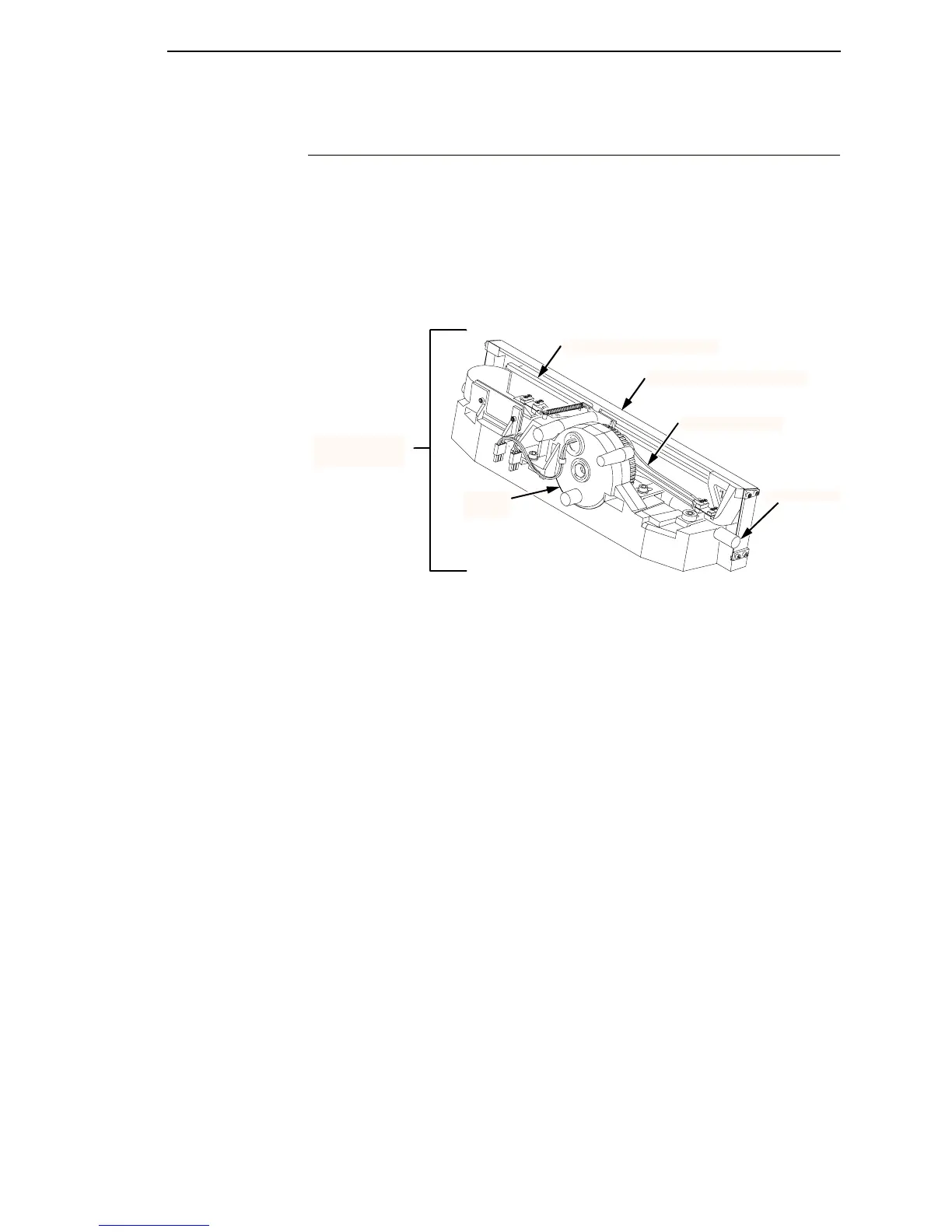
The central element of the printing mechanism is the shuttle frame assembly,
which houses the hammer bank assembly and the shuttle drive motor. (See
Figure 11.)
Figure 11. Shuttle Frame Assembly
Hammer Bank Assembly
The hammer springs are grouped in comb-like assemblies mounted on a solid
hammer bank. (See Figure 12.) Both the number of hammer springs per
hammer assembly and the number of hammer spring assemblies on the
hammer bank vary according to printer model:
• 6400-004/-04P/-005/-05P/-050/-P50: seven 4-hammer assemblies, for a
total of 28 hammer springs
• 6400-008/-08P/-009/-09P: seven 7-hammer assemblies, for a total of 49
hammer springs
• 6400-010 and -10P: six 10-hammer assemblies, for a total of 60 hammer
springs
• 6400-012/-014/-C05/-C5P: seven 13-hammer assemblies, for a total of 91
hammer springs
• 6400-015: six 17-hammer assemblies, for a total of 102 hammer springs
Shuttle Drive Motor
The shuttle drive motor is built into the shuttle assembly casting and drives
two connecting rods on a crankshaft. (See Figure 11.) The small end of one
connecting rod attaches to the hammer bank; the small end of the other
Shuttle Frame
Assembly
Hammer Bank Assembly
Counterweight Assembly
Connecting Rod
Guide Shaft
Shuttle
Motor

 Loading...


