Replacement
CPU
VRM
MEMOR
Y
HDD
PCI B
US
NMI
SMI
SER
VICE PR
OCESSOR
B
US
NON REDUND
ANT
PO
WER SUPPL
Y
1 2 3
A B
1 2 3
FAN
TEMPERA
TURE
1
2
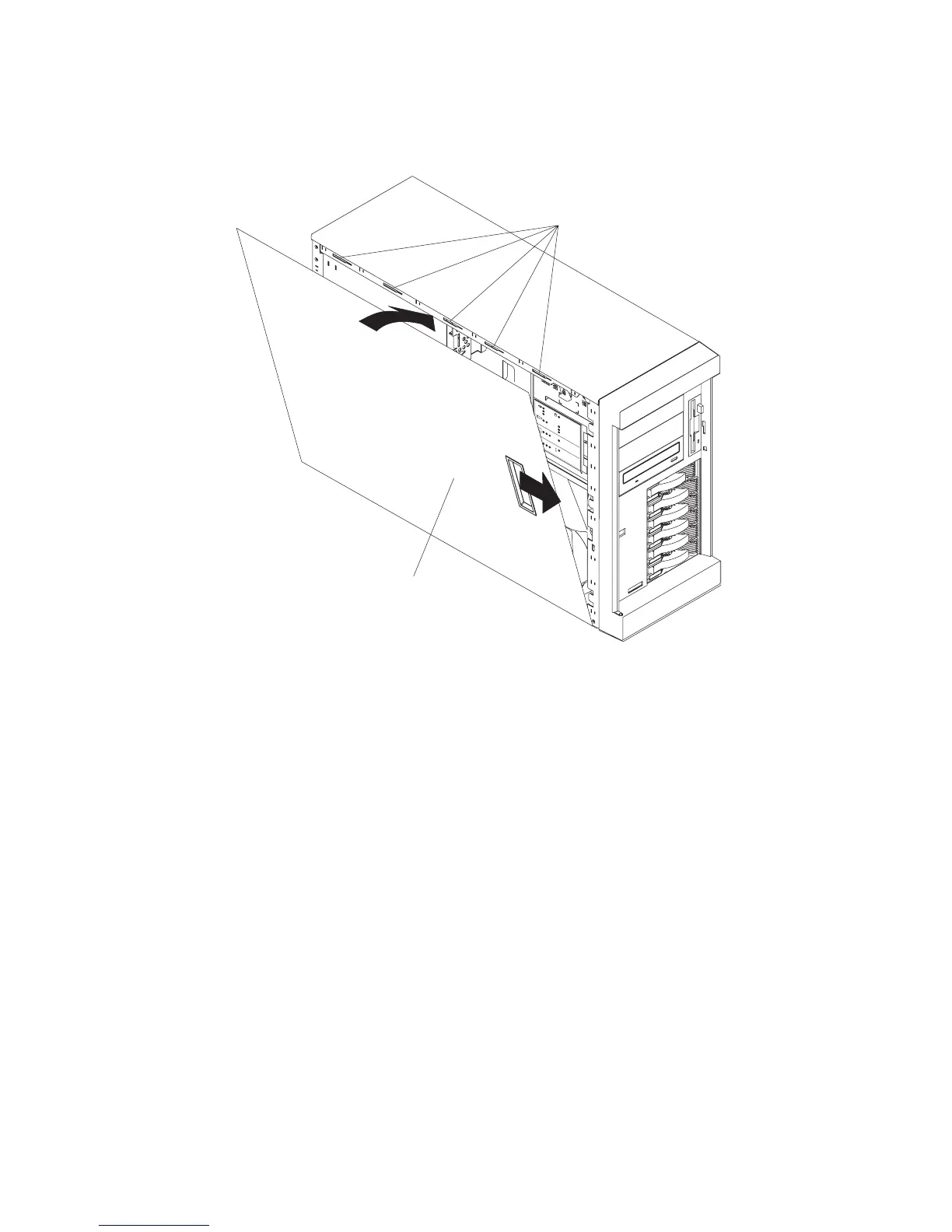
1. Align the service access cover (2) with the left side of the system, about 25 mm (1
inch) from the front of the system; place the bottom of the left-side cover on the
bottom rail of the left side of the chassis.
2. Insert the tabs at the top of the cover into the slots (1) at the top of the system side.
3. Hold the cover against the system, and slide the cover toward the front of the
system until the cover clicks into place.
Chapter 9. Removal and Replacement Procedures 259