NeoGCP i7 PLUS+
- 16 -
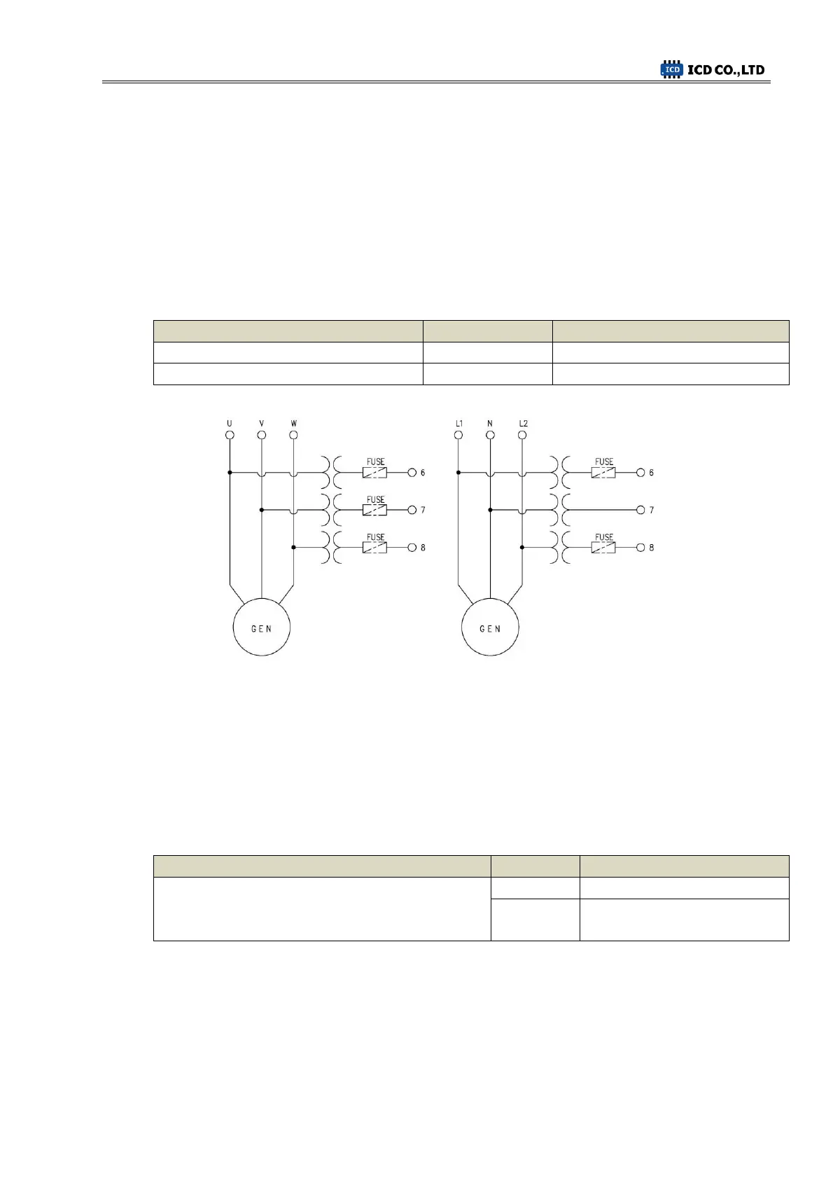
Number [6] ~ Number [9]GEN PT U, V, W, N 5.3.
- Detects generator voltage of Max AC 550[Vrms] by Numbers [6] ~ [9] ports.
- Wiring should be as follows.
1P-2W : L1-6, N-7 / 1P-3W : L1-6, N-7, L2-8 / 3P-3W : U-6, V-7, W-8 / 3P-4W : U-6, V-7,
W-8, N-9
- If generator voltage exceeds AC 550[Vrms], user should use PT(Potential Transformer) and
2
nd
Voltage should not exceed AC 550[Vrms].
Menus that are influenced
< GEN PT Wiring Example >
Number [10], Number [11] MPU ± 5.4.
- Detects magnetic pickup sensor input of Min 0.7[Vac] by numbers [10] and [11] ports.
- If [MENU]→[SYSTEM]→[ENGINE RPM]→[TEETH(FACTOR)] is set as 30,
RPM measurement will be in Frequency and do not use MPU.
Menus that are influenced
[SYSTEM] → [ENGINE RPM] → [TEETH(FACTOR)]
RPM measurement in Voltage
Number [12] ~ Number [14] RS485 ± 5.5.
- Sensing of RS485 ± by number [12] and [13] ports.
- Connect ports [13] and [14], then terminal resistance 120 [Ω] will be connected.