2
INSTALLATION AND CONNECTIONS
2-3
Connecting the AC power cable
D About the power supply voltage
90 ~ 132 V or
180 ~ 264 V AC (50 Hz/60 Hz) power source.
180 ~ 264 V
AC power source, the output power can be switched
between 1 kW and 500 W. (p. 4-2)
NOTE:
• 90 ~ 132 V AC
the period of transmission, we recommend using
a 180 ~ 264 V AC power source.
L To install a 180 ~ 264
licensed electrician.
• Only a 180 ~ 264 V AC power source can be used
for the EUR version.
D About an AC power plug
Use an AC power plug that matches the shape of the
outlet to be used because the plug is not included.
Connect each plug terminal to each wire (Blue or
White, Brown or Black, and Green/Yellow) of the AC
power cable that is connected to the power supply, as
shown below.
L AC input voltage is automatically recognized.
L
NOTE:
• The total current consumption is 19 ~ 21 A,
including the exciter.
considering the power consumption of household
electrical appliances (electric heaters, air
conditioners, microwave ovens, and so on).
• Icom is not responsible for any damage caused
by incorrect wiring of the AC power plug or power
failure.
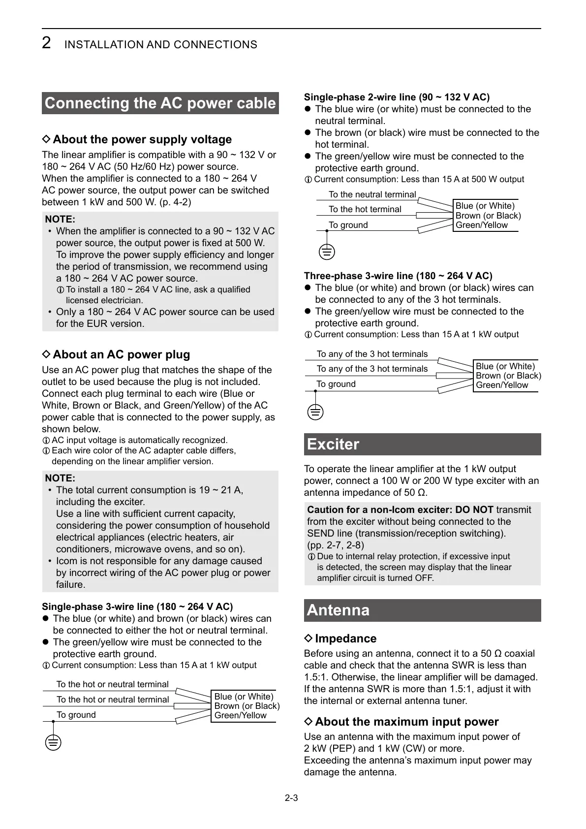
Single-phase 3-wire line (
180 ~ 264 V AC)
z The blue (or white) and brown (or black) wires can
be connected to either the hot or neutral terminal.
z The green/yellow wire must be connected to the
protective earth ground.
L
Blue (or White)
Brown (or Black)
Green/Yellow
To the hot or neutral terminal
To the hot or neutral terminal
To ground
Single-phase 2-wire line (90 ~ 132 V AC)
z The blue wire (or white) must be connected to the
neutral terminal.
z The brown (or black) wire must be connected to the
hot terminal.
z The green/yellow wire must be connected to the
protective earth ground.
L
Blue (or White)
Brown (or Black)
Green/Yellow
To the hot terminal
To the neutral terminal
To ground
Three-phase 3-wire line (180 ~ 264 V AC)
z The blue (or white) and brown (or black) wires can
be connected to any of the 3 hot terminals.
z The green/yellow wire must be connected to the
protective earth ground.
L
Blue (or White)
Brown (or Black)
Green/Yellow
To any of the 3 hot terminals
To any of the 3 hot terminals
To ground
Exciter
power, connect a 100 W or 200 W type exciter with an
Caution for a non-Icom exciter: DO NOT transmit
from the exciter without being connected to the
SEND line (transmission/reception switching).
(pp. 2-7, 2-8)
L Due to internal relay protection, if excessive input
is detected, the screen may display that the linear
Antenna
D Impedance
cable and check that the antenna SWR is less than
the internal or external antenna tuner.
D About the maximum input power
Use an antenna with the maximum input power of
2 kW (PEP) and 1 kW (CW) or more.
Exceeding the antenna’s maximum input power may
damage the antenna.