8-1
8
OTHER FUNCTIONS
Protection function
The Protection function monitors errors and load
status during operation.
If an abnormality occurs, the protection circuit turns
When the protection circuit is activated:
• Short beeps repeatedly sound.
• The indicator on
lights red.
• The meter display switches to a meter that
indicates abnormal values.
• The meter name indicator and protection readout
blink.
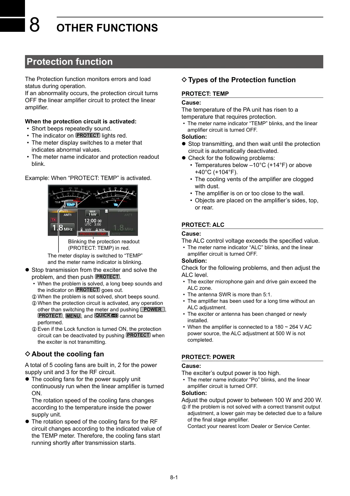
Example: When “PROTECT: TEMP” is activated.
Blinking the protection readout
(PROTECT: TEMP) in red.
The meter display is switched to “TEMP”
and the meter name indicator is blinking.
z Stop transmission from the exciter and solve the
problem, and then push
.
• When the problem is solved, a long beep sounds and
the indicator on
goes out.
L When the problem is not solved, short beeps sound.
L When the protection circuit is activated, any operation
other than switching the meter and pushing
,
,
, and
cannot be
performed.
L Even if the Lock function is turned ON, the protection
circuit can be deactivated by pushing
when
the exciter is not transmitting.
D About the cooling fan
A total of 5 cooling fans are built in, 2 for the power
supply unit and 3 for the RF circuit.
z The cooling fans for the power supply unit
ON.
The rotation speed of the cooling fans changes
according to the temperature inside the power
supply unit.
z The rotation speed of the cooling fans for the RF
circuit changes according to the indicated value of
the TEMP meter. Therefore, the cooling fans start
running shortly after transmission starts.
D Types of the Protection function
PROTECT: TEMP
Cause:
The temperature of the PA unit has risen to a
temperature that requires protection.
• The meter name indicator “TEMP” blinks, and the linear
Solution:
z Stop transmitting, and then wait until the protection
circuit is automatically deactivated.
z Check for the following problems:
• Temperatures below –10°C (+14°F) or above
+40°C (+104°F).
•
with dust.
•
•
or rear.
PROTECT: ALC
Cause:
• The meter name indicator “ALC” blinks, and the linear
Solution:
Check for the following problems, and then adjust the
ALC level.
• The exciter microphone gain and drive gain exceed the
ALC zone.
• The antenna SWR is more than 5:1.
•
ALC adjustment.
• The exciter or antenna has been changed or newly
installed.
•
power source, the ALC adjustment at 500 W is not
completed.
PROTECT: POWER
Cause:
• The meter name indicator “P” blinks, and the linear
Solution:
Adjust the output power to between 100 W and 200 W.
L If the problem is not solved with a correct transmit output
adjustment, a lower gain may be detected due to a failure
Contact your nearest Icom Dealer or Service Center.