INSTALLATION AND CONNECTIONS
2
2
2-4
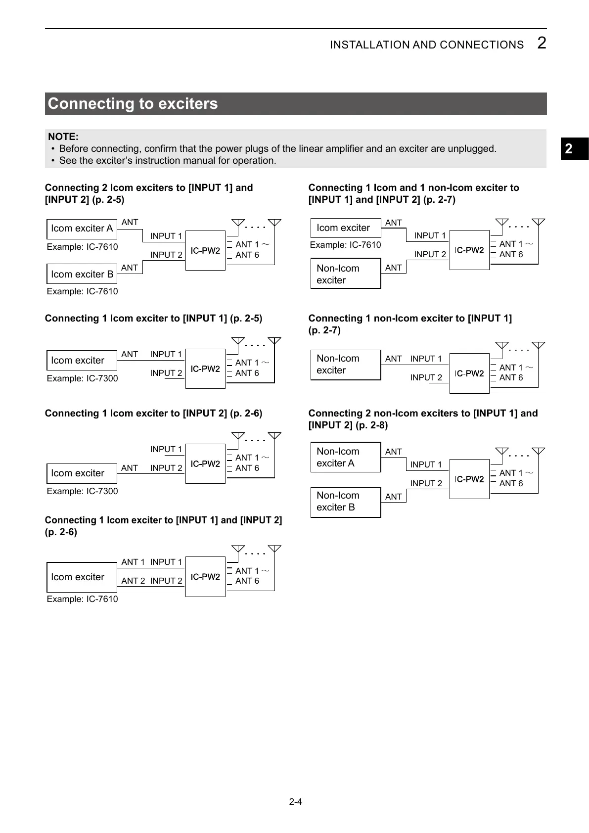
Connecting to exciters
NOTE:
•
• See the exciter’s instruction manual for operation.
Connecting 2 Icom exciters to [INPUT 1] and
[INPUT 2] (p. 2-5)
ANT 1 ~
ANT 6
INPUT 1
INPUT 2
ANT
ANT
Icom exciter A
Icom exciter B
Connecting 1 Icom exciter to [INPUT 1] (p. 2-5)
ANT 1 ~
ANT 6
INPUT 1
INPUT 2
ANT
Icom exciter
Connecting 1 Icom exciter to [INPUT 2] (p. 2-6)
ANT 1 ~
ANT 6
INPUT 1
INPUT 2ANT
Icom exciter
Connecting 1 Icom exciter to [INPUT 1] and [INPUT 2]
(p. 2-6)
ANT 1 ~
ANT 6
INPUT 1
INPUT 2
ANT 1
ANT 2
Icom exciter
Connecting 1 Icom and 1 non-Icom exciter to
[INPUT 1] and [INPUT 2] (p. 2-7)
ANT 1 ~
ANT 6
INPUT 1
INPUT 2
ANT
ANT
Icom exciter
Non-Icom
exciter
Connecting 2 non-Icom exciters to [INPUT 1] and
[INPUT 2] (p. 2-8)
ANT 1 ~
ANT 6
INPUT 1
INPUT 2
ANT
ANT
Non-Icom
exciter A
Non-Icom
exciter B
Connecting 1 non-Icom exciter to [INPUT 1]
(p. 2-7)
ANT 1 ~
ANT 6
INPUT 1
INPUT 2
ANT
Non-Icom
exciter