CONNECTOR INFORMATION
12
12
12-2
[REMOTE 1]/[REMOTE 2]
Connects to an Icom exciter to remotely
commands.
L [REMOTE 1] corresponds to the exciter
connected to [INPUT 1].
[REMOTE 2] corresponds to the exciter connected to
[INPUT 2].
NOTE: BE SURE to connect one-to-one with an
Icom exciter.
multiple units using a CI-V level converter.
[SEND 1]/[SEND 2]
Connects to a non-Icom exciter to
L See pages 2-7 and 2-8 for connecting with a
non-Icom exciter.
L
transmits.
L [SEND 1] corresponds to the exciter connected to [INPUT 1].
[SEND 2] corresponds to the exciter connected to [INPUT 2].
[ALC 1]/[ALC 2]
z Connect to output the ALC voltage to a
non-Icom exciter.
z When an Icom exciter is connected, and
the Digital Pre-Distortion (DPD) function is
used, outputs the feedback signal.
L [ALC 1] corresponds to the exciter connected to [INPUT 1].
[ALC 2] corresponds to the exciter connected to [INPUT 2].
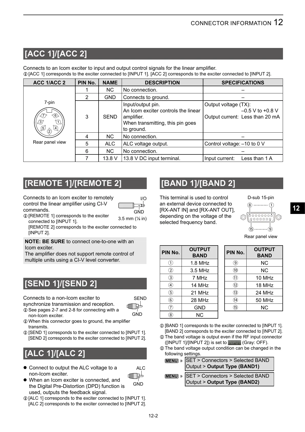
[ACC 1]/[ACC 2]
L [ACC 1] corresponds to the exciter connected to [INPUT 1]. [ACC 2] corresponds to the exciter connected to [INPUT 2].
ACC 1/ACC 2 PIN No. NAME DESCRIPTION SPECIFICATIONS
1
2
3
4
5
67
1 NC No connection. –
2 GND Connects to ground. –
3 SEND
Input/output pin.
An Icom exciter controls the linear
When transmitting, this pin goes
to ground.
Output voltage (TX):
–0.5 V to +0.8 V
Output current: Less than 20 mA
4 NC No connection. –
5 ALC ALC voltage output. Control voltage: –10 to 0 V
6 NC No connection. –
7 13.8 V 13.8 V DC input terminal. Input current: Less than 1 A
Rear panel view
7-pin
GND
SEND
GND
ALC
[BAND 1]/[BAND 2]
This terminal is used to
control
an external device connected to
[RX-ANT IN] and [RX-ANT OUT],
depending on the voltage of the
selected frequency band.
PIN No.
OUTPUT
BAND
1
2
3
4
5
6
7
GND
8
NC
PIN No.
OUTPUT
BAND
9
NC
#
NC
$
%
&
'
(
NC
L [BAND 1] corresponds to the exciter connected to [INPUT 1].
[BAND 2] corresponds to the exciter connected to [INPUT 2].
L The band voltage is output even if the RF input connector
([INPUT 1]/[INPUT 2]) is set to
(Gray: OFF).
L The band voltage output condition can be changed in the
following settings.
»
SET > Connectors > Selected BAND
Output > Output Type (BAND1)
»
SET > Connectors > Selected BAND
Output > Output Type (BAND2)
I/O
GND
18
9(
..........
.........
D-sub 15-pin
Rear panel view