12-1
12
CONNECTOR INFORMATION
[REMOTE AUX]
(Turning the power ON or OFF, and so
on) or an external device, such as an
antenna rotator controller or a band
decoder, using CI-V commands.
L When sending information, such as the frequency band of
be required.
»
SET > Connectors > CI-V
[INPUT 1/2]
Connects to an external device to
control the operations of [INPUT 1]
and [INPUT 2].
L The switching operation between
[INPUT 1] and [INPUT 2] according to
the signal (Low or Open) input from the
external device can be changed in the
following setting.
»
SET > Connectors >
INPUT1/2 Selection Input
L When the option to set (2) to unconnected is selected in
the INPUT1/2 Selection Input setting, the stereo mini plug
operates as a monaural mini plug.
[INPUT 1]/[INPUT 2]
Connects to an antenna connector of an
exciter using a coaxial cable.
•
(unbalanced)
L Connect an exciter with a maximum transmit output
power of 100 or 200 W.
L After connecting an exciter, select an appropriate option
in the following setting.
»
EXCITER > Exciter Connection
[RX-ANT IN]/[RX-ANT OUT]
Connects to an external unit,
inserted directly below each
antenna (ANT 1 ~ ANT 6).
•
• Connector type: BNC
L The ON/OFF setting of RX-I/O can be changed in the
ANTENNA SELECT screen of
(Lights green: RX
side). (p. 4-5)
L When the RX-I/O setting is enabled, a signal received
from ANT 1 ~ ANT 6 is output to [RX-ANT OUT].
A signal passed through an external device (example:
[RX-ANT IN].
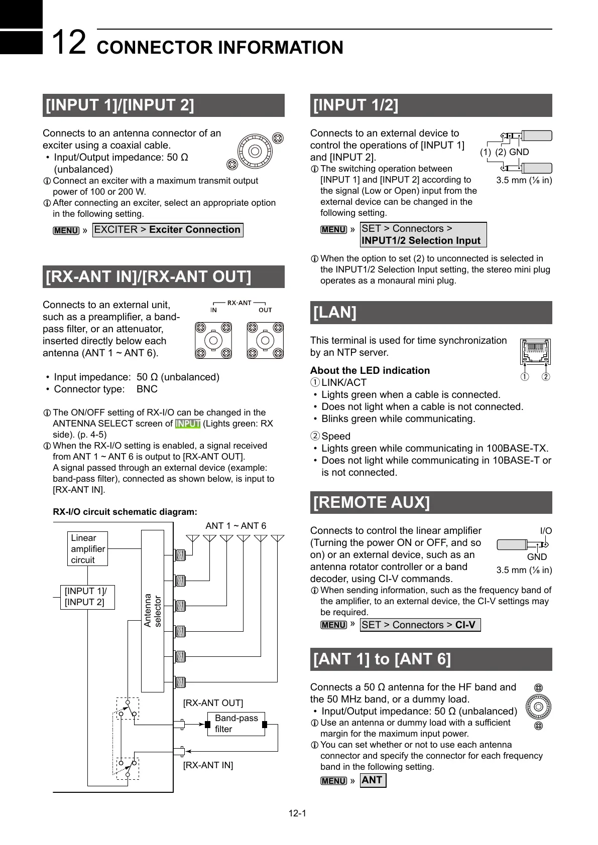
RX-I/O circuit schematic diagram:
ANT 1 ~ ANT 6
[RX-ANT IN]
[RX-ANT OUT]
Band-pass
Linear
circuit
[INPUT 1]/
[INPUT 2]
Antenna
selector
[ANT 1] to [ANT 6]
•
L
margin for the maximum input power.
L You can set whether or not to use each antenna
connector and specify the connector for each frequency
band in the following setting.
»
ANT
[LAN]
by an NTP server.
About the LED indication
1LINK/ACT
• Lights green when a cable is connected.
• Does not light when a cable is not connected.
• Blinks green while communicating.
2Speed
• Lights green while communicating in 100BASE-TX.
• Does not light while communicating in 10BASE-T or
is not connected.
q w
I/O
GND
(1) (2)
GND