2
INSTALLATION AND CONNECTIONS
2-7
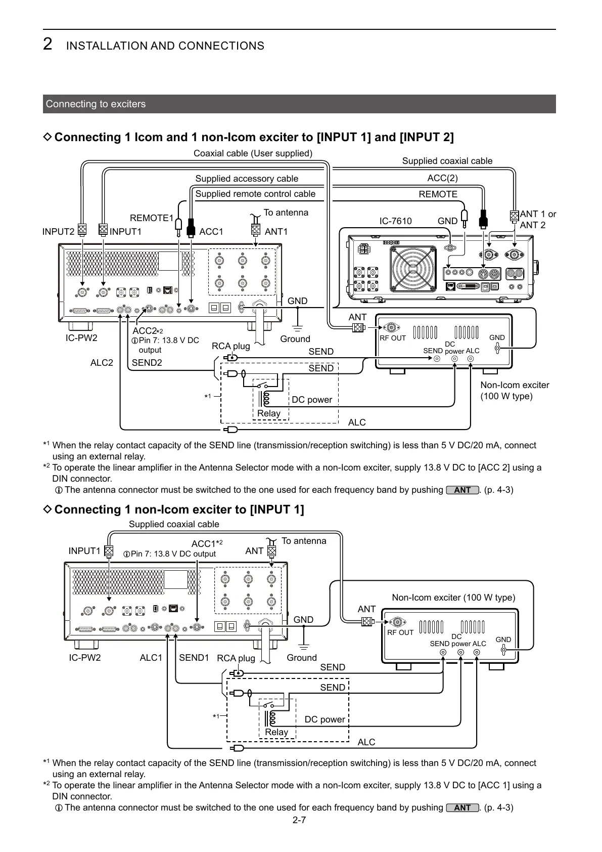
Connecting to exciters
D Connecting 1 Icom and 1 non-Icom exciter to [INPUT 1] and [INPUT 2]
D Connecting 1 non-Icom exciter to [INPUT 1]
IC-PW2
GND
ANT
INPUT1
SEND1
SEND
SEND
GND
ALCSEND
ANT
ALC1
ALC
REMOTE1
IC-PW2
ACC1
GND
ANT
INPUT1
IC-7610
ACC(2)
ANT1
SEND2
GND
REMOTE
ACC2
ALC2
SEND
SEND
GND
ALCSEND
ALC
Supplied coaxial cable
Coaxial cable (User supplied)
Ground
To antenna
Non-Icom exciter
(100 W type)
ANT 1 or
ANT 2
DC power
DC
power
RF OUT
L
output
Non-Icom exciter (100 W type)
Supplied coaxial cable
RCA plug
RCA plug
DC power
Relay
Relay
To antenna
Ground
DC
power
RF OUT
*
1
ACC1
L
*
1
When the relay contact capacity of the SEND line (transmission/reception switching) is less than 5 V DC/20 mA, connect
using an external relay.
*
2
DIN connector.
L The antenna connector must be switched to the one used for each frequency band by pushing
. (p. 4-3)
Supplied accessory cable
Supplied remote control cable
*
1
When the relay contact capacity of the SEND line (transmission/reception switching) is less than 5 V DC/20 mA, connect
using an external relay.
*
2
DIN connector.
L The antenna connector must be switched to the one used for each frequency band by pushing
. (p. 4-3)
*
2
*
1
*
2