EasyManuals Logo
Home>IDS>Digital Camera>uEye series

IDS uEye series User Manual

IDS uEye series
226 pages
To Next Page IconTo Next Page
To Previous Page IconTo Previous Page
Page #199 background imageLoading...
Page #199 background image
© 2009 IDS Imaging Development Systems GmbH 199
9 Specifications
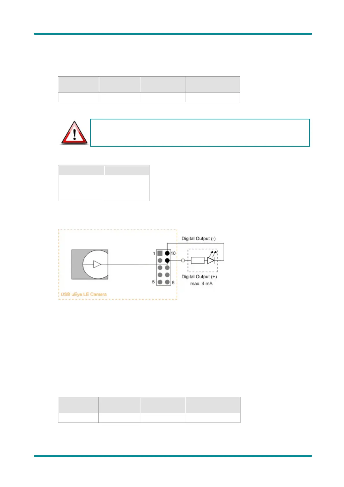
Digital Output Wiring (Flash)
Digital output specifications
Max. signal
level Low
Min. signal
level High
Max. signal level
High
Max. output current
0.4 V
2.4 V
3.0 V or 3.3 V
*1)
4 mA
*1) This voltage depends on the supply voltage required for the sensor used (see table below)
The digital output of the USB uEye LE is not potential-free and has no protective circuits.
Internal supply voltage by sensor type
3.0 V
3.3 V
164xLE
155xLE
148xLE
122xLE
154xLE
146xLE
Digital output wiring
Figure 184: Digital output wiring
General Purpose I/O Wiring
GPIO specifications
The two GPIOs (General Purpose I/O) can be used as inputs or outputs. This selection is made by
software using the corresponding SDK API functions. Please observe the following criteria:
· Input: 3.3 V LVTTL, max. 3.3 V input voltage
· Output: 3.3 V LVTTL, max. 4 mA
Max. signal
level Low
Min. signal level
High
Max. signal level
High
Max. output current
0.4 V
2.4 V
3.0 V or 3.3 V
*1)
4 mA
*1) This voltage depends on the supply voltage required for the sensor used (see table below)

Table of Contents

Questions and Answers:

Question and Answer IconNeed help?

Do you have a question about the IDS uEye series and is the answer not in the manual?

IDS uEye series Specifications

General IconGeneral
BrandIDS
ModeluEye series
CategoryDigital Camera
LanguageEnglish