Chapter 3 Welder Operation Description 53
Ehave Series Full Digital IGBT CO
2
/MAG/MMA Multifunctional Inverter Welder User Manual
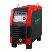
3. If the lock password is entered correctly, the screens display L good. See Figure 3-35.
The screens flash and the UI for locking the current adjustment range is displayed.
Figure 3-35 Message indicating that the lock password is entered correctly
If the lock password is not entered correctly, the screens display o FAIL. See Figure 3-28.
The UI for entering the lock password is displayed. See Figure 3-26.
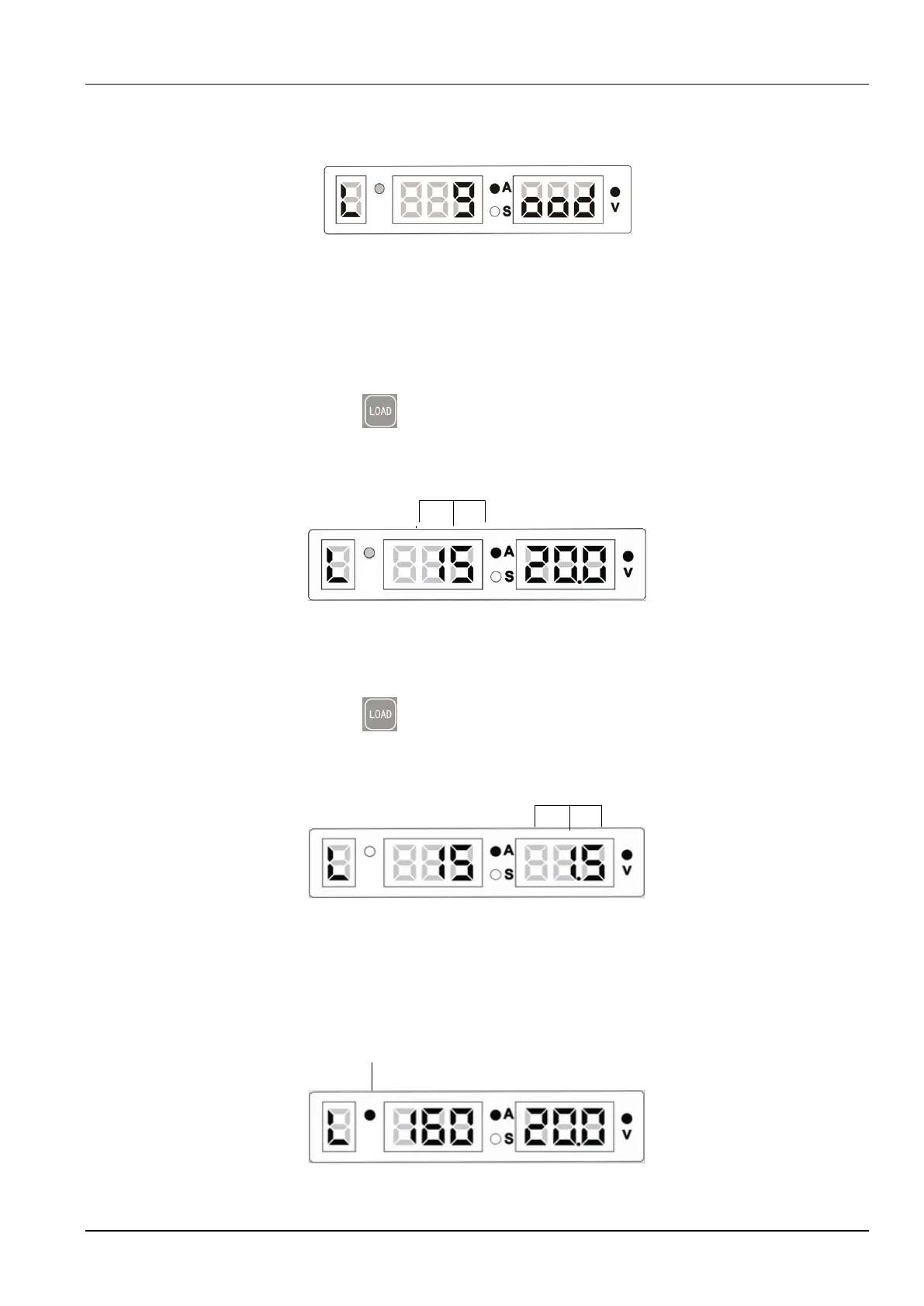
4. On the UI for locking the current adjustment range, the middle screen flashes. See Figure
3-36. Use the knob on the control panel of the welder to set the current adjustment range
and press the LOAD button. The UI for locking the voltage adjustment range is
displayed. The default range is ±15 A.
Flashing current value
Job No.
Figure 3-36 UI for locking the current adjustment range
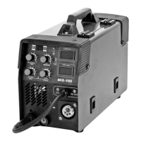
5. On the UI for locking the voltage adjustment range, the right screen flashes. See Figure
3-37. Use the knob on the control panel of the welder to set the voltage adjustment range
and press the LOAD button. The welder enters the state where the welding
parameter adjustment ranges are locked. The default range is ±1.5 V.
Flashing voltage value
Job No.
Figure 3-37 UI for locking the voltage adjustment range
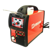
6. In the state where parameters are locked, the Job No. indicator flashes. See Figure 3-38.
The current and voltage adjustment ranges are locked. In the state, you can perform
welding and adjust the current and voltage within the specified ranges.
Flashing Channel indicator
Job No.
Figure 3-38 UI indicating that welding parameter adjustment ranges are locked