4 - 1
IPN 074-505-P1E
IC6 Operating Manual
Chapter 4
Sensor & Source Set-Up
4.1 Sensor Set-Up Introduction
The basic IC6 has one sensor measurement board with two sensor channels,
identified as CH1 and CH2 on the IC6 back panel and as Sensor # 1 and
Sensor # 2 on the display screens. Three more sensor measurement boards can
be added to support up to eight sensors. The second sensor measurement board
will normally be installed in the next slot labeled CH3 and CH4 and the associated
sensors will be Sensor# 3 and Sensor# 4 etc. Each sensor connection requires an
external oscillator (XIU) package.
Sensor Set-Up is initiated by moving the cursor to the Sensor heading on the Main
Menu and pressing MENU. To return to the Main Menu display, press MENU again.
4.1.1 Sensor Display Navigation
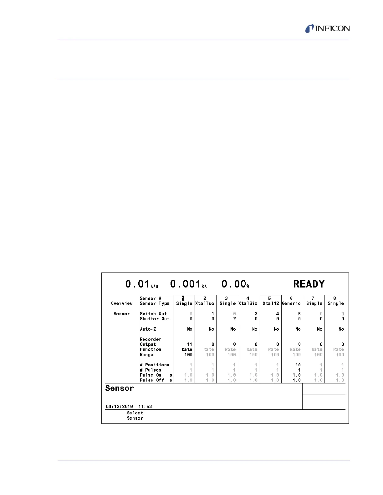
The Sensor Overview display, see Figure 4-1, shows the current configuration of
all eight possible sensors even if only one measurement board is installed.
To make changes, use the left/right cursor to move to the appropriate sensor, then
press F1 Select Sensor to bring up that sensor’s screen. See Figure 4-2.
Figure 4-1 Sensor overview